
Page 305 - Rashid, Power Electronics Handbook
P. 305
15 Resonant and Soft-Switching Converters 295
15.14.1 Resonant (Pulsating) dc link inverter
A resonant dc link converter for dc-ac power conversion was
proposed in 1986 [39]. Instead of using a nominally constant V0
dc link voltage, a resonant circuit is added to cause the dc link
voltage to pulsate at a high frequency. This resonant circuit
theoretically creates periodic zero-voltage duration at which
the inverter switches can be turned on or off. Figure 15.46 VA
shows the schematics of the pulsating link inverter. Typical dc
link voltage, inverter's phase voltage, and the line voltages are
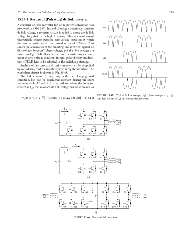
shown in Fig. 15.47. Because the inverter switching can only
occur at zero voltage duration, integral pulse density modula- VB
tion (IPDM) has to be adopted in the switching strategy.
Analysis of the resonant dc link converter can be simpli®ed
by considering that the inverter system is highly inductive. The
equivalent circuit is shown in Fig. 15.48.
VA-B
The link current I may vary with the changing load
x
condition, but can be considered constant during the short
resonant cycle. If switch S is turned on when the inductor
current is I , the resonant dc link voltage can be expressed as
Lo
FIGURE 15.47 Typical dc link voltage (V 0 ), phase voltages (V A ; V B ),
V ðtÞ¼ V þ e ÿat ÿV cosðotÞþ oLI sinðotÞ ð15:14Þ
c s s M and line voltage (V AB ) of resonant link inverters.
L
I
L
S1 S2 S3
C VA
V VB
S
VC
S S4 S5 S6
(a)
I
L X
I
L
S1 S2 S3
VA
V C VB
S
VC
S4 S5 S6
(b)
L
S1 S2 S3 S7 S8 S9
3 phase C To
AC Load
C
r
S4 S5 S6 S10 S11 S12
(c)
FIGURE 15.46 Resonant-link inverters.