
Page 304 - Rashid, Power Electronics Handbook
P. 304
294 S. Hui and H. Chung
nant pole idea. By incorporating the ®lter components into the
inverter operation, resonance condition and thus zero volta-
ge=current conditions can be created for the inverter switches.
In this section, the following soft-switched inverters are
described.
Approach A: Resonant dc link inverters:
1. resonant (pulsating) dc link inverters;
2. actively-clamped resonant dc link inverters;
3. resonant inverters with minimum voltage stress;
4. quasi-resonant soft-switched inverter; and
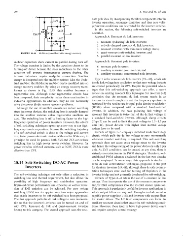
FIGURE 15.45 McMurray snubber with energy recovery.
5. parallel resonant dc link inverter.
snubber capacitors share current in parallel during turn off. Approach B: Resonant pole inverters:
The voltage transient is limited by the capacitor closest to the 6. resonant pole inverters;
turning-off device because the stray inductance to the other 7. auxiliary resonant pole inverters; and
capacitor will prevent instantaneous current sharing. The 8. auxiliary resonant commutated pole inverters.
turn-on inductors require midpoint connection. Snubber
energy is dissipated into the snubber resistor. Like the Unde- Type 1 is the resonant dc link inverter [39 – 41], which sets
land snubber, the McMurray snubber can be modi®ed into an the dc link voltage into oscillation so that zero-voltage instants
energy recovery snubber. By using an energy recovery trans- are created periodically for ZVS. Despite the potential advan-
former as shown in Fig. 15.45. this snubber becomes a tages that this soft-switching approach can offer, a recent
regenerative one. Although other regenerative circuits have review on existing resonant link topologies for inverters [42]
been proposed, their complexity makes them unattractive in concludes that the resonant dc link system results in an
industrial applications. In addition, they do not necessarily increase in circuit complexity and the frequency spectrum is
solve the power diode reverse recovery problems. restricted by the need to use integral pulse density modulation
Although the use of snubber circuits can reduce switching (IPDM) when compared with a standard hard-switched
stress in power devices, the switching loss is actually damped inverter. In addition, the peak pulsating link voltage of
into the snubber resistors unless regenerative snubbers are resonant link inverters is twice that of the dc link voltage in
used. The switching loss is still a limiting factor to the high a standard hard-switched inverter. Although clamp circuits
frequency operation of power inverters. However, the advent (Type 2) can be used to limit the peak voltage to 1.3 – 1.5 per
of soft-switching techniques opens up a new way to use high- unit [41], power devices with higher than normal voltage
frequency inverter operation. Because the switching trajectory ratings have to be used.
of a soft-switched switch is close to the voltage and current Circuits of Types 3 – 5 employ a switched mode front stage
axis, faster power electronic devices with smaller SOAs can, in circuit, which pulls the dc link voltage to zero momentarily
principle, be used. In general, both ZVS and ZCS can reduce whenever inverter switching is required. This soft-switching
switching loss in high-power power switches. However, for approach does not cause extra voltage stress to the inverter
power switches with tail currents, such as IGBT, ZCS is more and hence the voltage rating of the power devices is only 1 per
effective than ZVS. unit. As ZVS conditions can be created at any time, there is
virtually no restriction in the PWM strategies. Therefore, well-
established PWM schemes developed in the last two decades
can be employed. In some ways, this approach is similar to
15.14 Soft-Switching DC-AC Power some dc-side commutation techniques proposed in the past
Inverters for thyristor inverters [43, 44], although these dc-side commu-
tation techniques were used for turning off thyristors in the
The soft-switching technique not only offers a reduction in inverter bridge and not primarily developed for soft-switching.
switching loss and thermal requirement, but also allows the Circuits of Types 6 – 8 retain the use of a constant dc link
possibility of high frequency and snubberless operation. voltage. They incorporate the use of the resonant components
Improved circuit performance and ef®ciency as well as reduc- and=or ®lter components into the inverter circuit operation.
tion of EMI emission can be achieved. For zero voltage This approach is particularly useful for inverter applications in
switching (ZVS) inverter applications, two major approaches which output ®lters are required. Examples include uninter-
that enable inverters to be soft-switched have been proposed. ruptible power supplies (UPS) and inverters with output ®lters
The ®rst approach pulls the dc link voltage to zero momenta- for motor drives. The LC ®lter components can form the
rily so that the inverter's switches can be turned on and off auxiliary resonant circuits that create the soft-switching condi-
with ZVS. Resonant dc link and quasi-resonant inverters tions. However, these tend to have high-power device count
belong to this category. The second approach uses the reso- and require complex control strategy.