
Page 303 - Rashid, Power Electronics Handbook
P. 303
15 Resonant and Soft-Switching Converters 293
(a) (b)
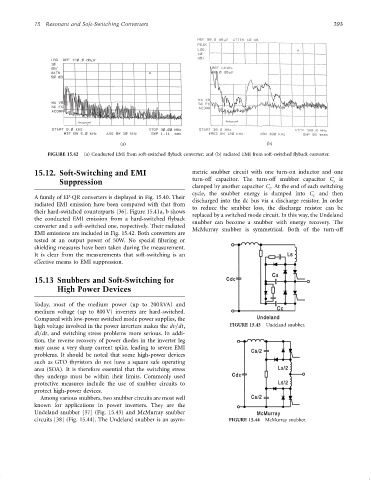
FIGURE 15.42 (a) Conducted EMI from soft-switched ¯yback converter; and (b) radiated EMI from soft-switched ¯yback converter.
15.12. Soft-Switching and EMI metric snubber circuit with one turn-on inductor and one
Suppression turn-off capacitor. The turn-off snubber capacitor C is
s
clamped by another capacitor C . At the end of each switching
c
cycle, the snubber energy is dumped into C and then
c
A family of EP-QR converters is displayed in Fig. 15.40. Their
discharged into the dc bus via a discharge resistor. In order
radiated EMI emission have been compared with that from
to reduce the snubber loss, the discharge resistor can be
their hard-switched counterparts [36]. Figure 15.41a, b shows
replaced by a switched mode circuit. In this way, the Undeland
the conducted EMI emission from a hard-switched ¯yback
snubber can become a snubber with energy recovery. The
converter and a soft-switched one, respectively. Their radiated
McMurray snubber is symmetrical. Both of the turn-off
EMI emissions are included in Fig. 15.42. Both converters are
tested at an output power of 50W. No special ®ltering or
shielding measures have been taken during the measurement.
It is clear from the measurements that soft-switching is an
effective means to EMI suppression.
15.13 Snubbers and Soft-Switching for
High Power Devices
Today, most of the medium power (up to 200 kVA) and
medium voltage (up to 800 V) inverters are hard-switched.
Compared with low-power switched mode power supplies, the
high voltage involved in the power inverters makes the dv=dt, FIGURE 15.43 Undeland snubber.
di=dt, and switching stress problems more serious. In addi-
tion, the reverse recovery of power diodes in the inverter leg
may cause a very sharp current spike, leading to severe EMI
problems. It should be noted that some high-power devices
such as GTO thyristors do not have a square safe operating
area (SOA). It is therefore essential that the switching stress
they undergo must be within their limits. Commonly used
protective measures include the use of snubber circuits to
protect high-power devices.
Among various snubbers, two snubber circuits are most well
known for applications in power inverters. They are the
Undeland snubber [37] (Fig. 15.43) and McMurray snubber
circuits [38] (Fig. 15.44). The Undeland snubber is an asym- FIGURE 15.44 McMurray snubber.