
Page 263 - Semiconductor For Micro- and Nanotechnology An Introduction For Engineers
P. 263
Interacting Subsystems
100A
o
f o = 420MHz
f
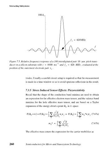
Figure 7.5. Relative frequency response of a 100 interdigitated pair 10 µm pitch trans-
– 1
ducer on a silicon substrate with c = 8400 ms and f = 420 MHz , evaluated at the
o
position of the outermost electrode pair x .
o
trodes. Usually a careful circuit setup is required so that the measurement
is made in a time window so as to avoid spurious reflections in the result.
7.3.5 Stress Induced Sensor Effects: Piezoresistivity
Recall that the shape of the conduction band minima are used to obtain
an expression for the effective electron mass tensor, and the valence band
maxima for the hole effective mass tensor, and are based on a Taylor
expansion of the energy about a point k in -space
k
0
2
1 ∂ E 1
(
(
(
E k + κ) ≈ E k ) + --- ∑ ---------------κ κ = E k ) + --- ∑ m ∗ κ κ (7.67a)
0 0 i j 0 ij i j
2 ∂k ∂k j 2
i
ij ij
2
1 ∂ E
m ∗ = --- ∑ --------------- (7.67b)
ij 2 ∂k ∂k
ij i j
The effective mass enters the expression for the carrier mobilities as
260 Semiconductors for Micro and Nanosystem Technology