
Page 111 - Semiconductor Manufacturing Handbook
P. 111
Geng(SMH)_CH09.qxd 04/04/2005 19:42 Page 9.10
MICROLITHOGRAPHY
9.10 WAFER PROCESSING
difficult to solve without the aid of a powerful computer. A simpler approach is to artificially decou-
ple the electric and magnetic field vector components and describe light as a scalar quantity, and then
to use simplified (assumed) boundary conditions. Under most conditions scalar diffraction theory is
surprisingly accurate. In lithography, the distance from the mask to the objective lens is very large, so
that the scalar diffraction theory is at its simplest, called Fraunhofer diffraction.
In order to establish a mathematical description of diffraction by a mask, let us describe the elec-
tric field transmittance of a mask pattern as t (x, y), where the mask is in the x − y plane and t (x, y)
m m
has in general both magnitude and phase. For a simple chrome-glass mask, the mask transmittance
is assumed to be binary—t (x, y) is 1 under the glass and 0 under the chrome. Let the x′ − y′ plane
m
be the diffraction plane, that is, the entrance to the objective lens, and let z be the distance from the
mask to the objective lens. Finally, we will assume a monochromatic light of wavelength l and that
the entire system is in air (so that its index of refraction can be dropped). Then, the electric field of
our diffraction pattern T (x′, y′) is given by the Fraunhofer diffraction integral
m
x +
(
( ′′
T x y ) = ∫ ∞ ∫ ∞ t x y e −2p if x f y) dxdy (9.2)
y
)
(
,
,
m −∞ −∞ m
where fx = x′/(zl) and fy = y′/(zl) and are called the spatial frequencies of the diffraction pattern.
For many scientists and engineers, this equation should be quite familiar—it is simply a Fourier
transform. Thus, the diffraction pattern (i.e., the electric field distribution as it enters the objective
lens) is just the Fourier transform of the mask pattern. This is the principle behind an extremely use-
ful approach to imaging called Fourier optics.
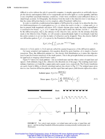
Figure 9.7 shows two mask patterns—one an isolated space and the other a series of equal lines and
spaces—both infinitely long in the y direction (the direction out of the page). The resulting mask trans-
mittance functions t (x) look like a square pulse and a square wave, respectively. The Fourier transforms
m
are easily found in tables or directly calculated and are also shown in Fig. 9.7. The isolated space gives
rise to a sinc function diffraction pattern, and the equal lines and spaces yield discrete diffraction orders.
sin(p wf )
Isolated space: Tx() ′ = x
m
p f x
∞ n
Dense space: Tx () ′ = 1 ∑ sin(p wf ) d f − (9.3)
x
m
p n=−∞ p f x x p
Mask
1
t (x) 0
m
T (x′) f
m
0 0 x
(a) (b)
FIGURE 9.7 Two typical mask patterns—an isolated space and an array of equal lines and
spaces—and the resulting Fraunhofer diffraction patterns assuming normally incident plane wave
illumination.
Downloaded from Digital Engineering Library @ McGraw-Hill (www.digitalengineeringlibrary.com)
Copyright © 2004 The McGraw-Hill Companies. All rights reserved.
Any use is subject to the Terms of Use as given at the website.