
Page 112 - Semiconductor Manufacturing Handbook
P. 112
Geng(SMH)_CH09.qxd 04/04/2005 19:42 Page 9.11
MICROLITHOGRAPHY
MICROLITHOGRAPHY 9.11
where δ = Dirac delta function
w = space width
p = pitch (the linewidth plus the space width)
Let’s take a closer look at the diffraction pattern for equal lines and spaces. Note that the graphs
of the diffraction patterns in Fig. 9.7 use spatial frequency as its x-axis. Since z and l are fixed for a
given optical system, the spatial frequency is simply a scaled x′ coordinate. At the center of the
objective lens entrance (fx = 0), the diffraction pattern has a bright spot called the zero order. The
zero order is the light that passes through the mask and is not bent. The zero order can be thought of
as “DC” light, providing power but no information as to the size of the features on the mask. To
either side of the zero order are two peaks called the first diffraction orders. These peaks occur at
spatial frequencies of ±1/p, where p is the pitch of the mask pattern (linewidth plus spacewidth).
Since the position of these diffraction orders depends on the mask pitch, their position contains infor-
mation about the pitch. It is this information that the objective lens will use to reproduce the image
of the mask. In fact, in order for the objective lens to form a true image of the mask it must have the
zero order and at least one of the first orders. In addition to the first order, there can be many high-
er orders, with the nth order occurring at a spatial frequency of n/p.
9.2.2 Image Formation
We are now ready to describe what happens next and follow the diffracted light as it enters the objec-
tive lens. In general, the diffraction pattern extends throughout the x′− y′ plane. However, the objec-
tive lens, being only of finite size, cannot collect all of the light in the diffraction pattern. Typically,
lenses used in microlithography are circularly symmetric and the entrance to the objective lens can
be thought of as a circular aperture. Only those portions of the mask diffraction pattern that fall
inside the aperture of the objective lens go on to form the image. Of course we can describe the size
of the lens aperture by its radius, but a more common and useful description is to define the maxi-
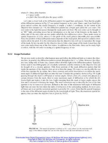
mum angle of diffracted light that can enter the lens. Consider the geometry shown in Fig. 9.8. Light
passing through the mask is diffracted at various angles. Given a lens of a certain size placed at a
certain distance from the mask, there is some maximum angle of diffraction a for which the dif-
fracted light just makes it into the lens. Light emerging from the mask at larger angles misses the
lens and is not used in forming the image. The most convenient way to describe the size of the lens
aperture is by its numerical aperture, defined as the sine of the maximum half-angle of diffracted
light that can enter the lens times the index of refraction of the surrounding medium. In most cases,
all lenses are in air and the numerical aperture is given by NA = sina. (Note that the spatial frequency
is the sine of the diffracted angle divided by the wavelength of light. Thus, the maximum spatial fre-
quency that can enter the objective lens is given by NA/l.)
Objective lens
α
Mask Aperture
FIGURE 9.8 The numerical aperture is defined as NA = sinα, where α is the maximum half-
angle of the diffracted light that can enter the objective lens (the lens and mask are in air).
Downloaded from Digital Engineering Library @ McGraw-Hill (www.digitalengineeringlibrary.com)
Copyright © 2004 The McGraw-Hill Companies. All rights reserved.
Any use is subject to the Terms of Use as given at the website.