
Page 236 - Semiconductor Manufacturing Handbook
P. 236
Geng(SMH)_CH16.qxd 04/04/2005 19:54 Page 16.3
ECD FUNDAMENTALS
ECD FUNDAMENTALS 16.3
Industrial processes are typically operated in current-control mode that is analogous to control-
ling the deposition rate. In such a case, the voltage increases to the point necessary to drive the chem-
ical reaction(s) necessary to support the current in the system.
The electrochemical reactions at the electrodes in an electrodeposition system consume reactants
and create reaction products. This leads to the importance of mass transfer to carry these reactants
and products to the surface of the electrode within the electrolyte. Typically, mass transfer effects
are explained relative to the metal being deposited at the cathode. It is important to remember,
however, that mass transfer is also critical for the other bath components and at the anode, as well
as the cathode.
In a typical ECD cell, the source of the metal being deposited is considered to be the electrolyte
very near the electrode (cathode). This is in contrast to a vacuum deposition process such as sput-
tering, in which the mean free path is very large and the source of the deposited material is the
counter-electrode, or target. The metal ions are consumed by the reduction reaction at the cathode
(Eq. (16.1a)) and the concentration of these ions is reduced in a region very near the electrode sur-
face. As the reaction proceeds, this leads to the formation of a region of reduced concentration called
the diffusion boundary layer. The concentration gradient in this diffusion boundary layer is the dri-
ving force for the transport of the ionic reactant to the cathode surface. The balance of the diffusion
rate to the reaction rate is a critical parameter in electrolytic systems.
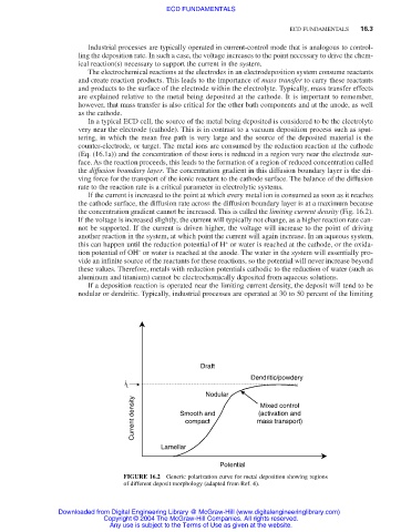
If the current is increased to the point at which every metal ion is consumed as soon as it reaches
the cathode surface, the diffusion rate across the diffusion boundary layer is at a maximum because
the concentration gradient cannot be increased. This is called the limiting current density (Fig. 16.2).
If the voltage is increased slightly, the current will typically not change, as a higher reaction rate can-
not be supported. If the current is driven higher, the voltage will increase to the point of driving
another reaction in the system, at which point the current will again increase. In an aqueous system,
+
this can happen until the reduction potential of H or water is reached at the cathode, or the oxida-
−
tion potential of OH or water is reached at the anode. The water in the system will essentially pro-
vide an infinite source of the reactants for these reactions, so the potential will never increase beyond
these values. Therefore, metals with reduction potentials cathodic to the reduction of water (such as
aluminum and titanium) cannot be electrochemically deposited from aqueous solutions.
If a deposition reaction is operated near the limiting current density, the deposit will tend to be
nodular or dendritic. Typically, industrial processes are operated at 30 to 50 percent of the limiting
Draft
Dendritic/powdery
i L
Nodular Mixed control
Current density Smooth and mass transport)
(activation and
compact
Lamellar
Potential
FIGURE 16.2 Generic polarization curve for metal deposition showing regions
of different deposit morphology (adapted from Ref. 4).
Downloaded from Digital Engineering Library @ McGraw-Hill (www.digitalengineeringlibrary.com)
Copyright © 2004 The McGraw-Hill Companies. All rights reserved.
Any use is subject to the Terms of Use as given at the website.