
Page 296 - Semiconductor Manufacturing Handbook
P. 296
Geng(SMH)_CH19.qxd 04/04/2005 20:00 Page 19.23
INSPECTION, MEASUREMENT, AND TEST
INSPECTION, MEASUREMENT, AND TEST 19.23
PC workstation
controls all sites
PPS
PMU
PPMU
DUT
Vector DUT Site x
M DUT
memory DUT
U
X
Algorithmic Site 1
pattern
Test
generator
site M
controller U
Buffer X
memory
Error
catch
RAM
Site x
Site 1
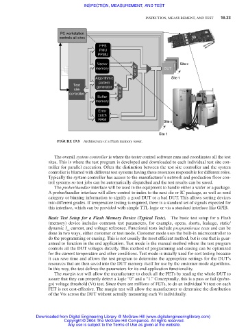
FIGURE 19.8 Architecture of a Flash memory tester.
The overall system controller is where the tester control software runs and coordinates all the test
sites. This is where the test program is developed and downloaded to each individual test site con-
troller for parallel execution. Often the distinction between the test site controller and the system
controller is blurred with different test systems having these resources responsible for different roles.
Typically the system controller has access to the manufacturer’s network and production floor con-
trol systems so test jobs can be automatically dispatched and the test results can be saved.
The prober/handler interface will be used in the equipment to handle either a wafer or a package.
A prober/handler interface will allow control to index to the next die or IC package, as well as send
category or binning information to signify a good DUT or a bad DUT. This allows sorting devices
into different grades. If temperature testing is required, there is a standard set of signals expected for
this interface, which can be provided with simple TTL logic or via a standard interface like GPIB.
Basic Test Setup for a Flash Memory Device (Typical Tests). The basic test setup for a Flash
(memory) device includes common test parameters, for example, opens, shorts, leakage, static/
dynamic I current, and voltage reference. Functional tests include program/erase tests and can be
cc
done in two ways, either customer or test mode. Customer mode uses the built-in microcontroller to
do the programming or erasing. This is not usually the most efficient method, but is one that is guar-
anteed to function in the end application. Test mode is the manual method where the test program
controls all the DUT voltages directly. This method of programming and erasing can be optimized
for the current temperature and other conditions. Test mode is usually used for sort testing because
it can save time and allows the test program to determine the appropriate settings for the DUT’s
resources that are then saved into the DUT memory itself for use by the customer mode algorithms.
In this way, the test defines the parameters for its end application functionality.
The margin test will allow the manufacturer to check all the FETs by reading the whole DUT to
assure that they can properly detect a logic “0” and a “1.” Conceptually, this is a pass or fail (go/no-
go) voltage threshold (Vt) test. Since there are millions of FETs, to do an individual Vt test on each
FET is not cost-effective. The margin test will allow the manufacturer to determine the distribution
of the Vts across the DUT without actually measuring each Vt individually.
Downloaded from Digital Engineering Library @ McGraw-Hill (www.digitalengineeringlibrary.com)
Copyright © 2004 The McGraw-Hill Companies. All rights reserved.
Any use is subject to the Terms of Use as given at the website.