
Page 249 - Sustainability in the Process Industry Integration and Optimization
P. 249
226 Cha p te r T e n
(a) CP [kW/°C]
121°C 163.4°C 249°C
E4 E1 4 17
CP=9.1 kW/°C
E2
66°C 103.1°C 305°C
C E3 5 13
CP=3.9 kW/°C
482 kW
38°C 205°C
1 E2 11
1837 kW
66°C 121.43°C 182°C 13
2 E4 E3
720 kW 788 kW
93°C 205°C
3 E1 13
1456 kW
One possible design
(b) CP [kW/°C]
CP=5.22 kW/°C
E3
E1 17
121°C 249°C
E2 4
CP=11.78 kW/°C
66°C 103.1°C 193°C 305°C
C E4 E1 5 13
482 kW
38°C 144.3°C 205°C
1 E4 E3 11
1169 kW 668.16 kW
66°C 182°C 13
2 E2
1508 kW
93°C 205°C
3 E1
13
1456 kW
A second possible design
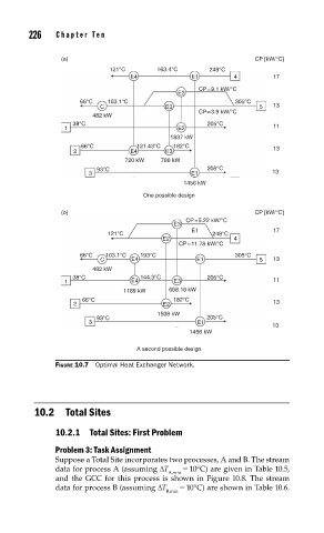
FIGURE 10.7 Optimal Heat Exchanger Network.
10.2 Total Sites
10.2.1 Total Sites: First Problem
Problem 3: Task Assignment
Suppose a Total Site incorporates two processes, A and B. The stream
data for process A (assuming ΔT = 10°C) are given in Table 10.5,
A,min
and the GCC for this process is shown in Figure 10.8. The stream
data for process B (assuming ΔT = 10°C) are shown in Table 10.6.
B,min