Page 97 - Sustainability in the Process Industry Integration and Optimization
P. 97

74   Cha p te r  F o u r


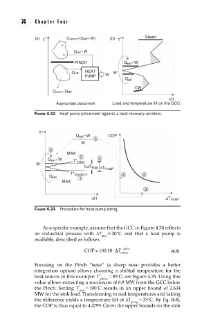
                     (a)  T *     Q Hmin–(Q HP+W)  (b)  T *      Steam

                                     Q HP+W

                                     PINCH              Q HP +W
                                         HEAT
                                    Q HP         W  W
                                         PUMP
                                                         Q HP
                                                             CW
                            Q cmin–Q HP
                                                                          ΔH
                              Appropriate placement  Load and temperature lift on the GCC
                     FIGURE 4.32  Heat pump placement against a heat recovery problem.


                       T*
                                     Q HP +W      COP
                                             5
                                       W
                           6
                                  MAX
                                       2
                          Q HP +W             3
                      W             T* SINK
                                        ½ΔT min  ΔT PUMP
                                   T* SOURCE            4       4
                           Q HP
                                       1
                                MAX
                                                                 3
                                            ΔH                           ΔT PUMP
                     FIGURE 4.33  Procedure for heat-pump sizing.


                        As a specific example, assume that the GCC in Figure 4.34 reflects
                     an industrial process with ΔT   = 20°C and that a heat pump is
                                               min
                     available, described as follows:


                                                    ˜
                                                        0.874
                                         COP 100.18   T pump               (4.8)
                     Focusing on the Pinch “nose” (a sharp nose provides a better
                     integration option) allows choosing a shifted temperature for the
                                               *    = 85˚C; see Figure 4.35. Using this
                                               source
                     heat source, in this example: T
                     value allows extracting a maximum of 6.9 MW from the GCC below
                                       *    = 100˚C results in an upper bound of 2.634
                                       sink
                     the Pinch. Setting T
                     MW for the sink load. Transforming to real temperatures and taking
                     the difference yields a temperature lift of ΔT   = 35°C. By Eq. (4.8),
                                                           pump
                     the COP is thus equal to 4.4799. Given the upper bounds on the sink
   92   93   94   95   96   97   98   99   100   101   102