
Page 96 - Sustainability in the Process Industry Integration and Optimization
P. 96
P r o c e s s I n t e g r a t i o n f o r I m p r ov i n g E n e r g y E f f i c i e n c y 73
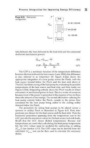
FIGURE 4.31 Heat-pump T*
confi guration. Sink
Q+W=125 kW
T* sink
W=25 kW
Q=100 kW
T* source
Source
ratio between the heat delivered to the heat sink and the consumed
shaftwork (mechanical power):
Q sink Q source W (4.6)
COP Q sink = Q source W (4.7)
W W
The COP is a nonlinear function of the temperature difference
between the heat sink and the heat source (Laue, 2006); this difference
is also referred to as temperature lift. Figure 4.32(a) shows the
appropriate integration of a heat pump across the Pinch, with the
heat source located below the Pinch and the heat sink above it.
The GCC facilitates sizing of the heat pump by evaluating the possible
temperatures of the heat source and heat sink, and their loads; see
Figure 4.32(b). Integrating entirely above the Pinch results in direct
conversion of mechanical power to heat. This is a waste of resources
because most of the power is generated at the expense of two to three
times the amount of fuel energy. The second alternative—placing the
heat pump entirely below the Pinch—results in the power flow
consumed by the heat pump being added to the cooling utility
demand below the Pinch.
The procedure for sizing heat pumps to be placed across a
(process or utility) Pinch is illustrated in Figure 4.33. First, tem-
peratures are chosen for the heat source and the heat sink. Then the
horizontal projections spanning from the temperature axis to the
GCC provide the maximum values for the heat source and sink loads.
Recall that the GCC shows shifted temperatures. Because real
temperatures are used when calculating the heat-pump temperature
lift, the GCC values must be modified by subtracting or adding
ΔT /2 (see Section 4.3.3). The COP value can be derived from the
min
calculated ΔT and can be then used to calculate the necessary
pump
duties.