
Page 93 - Sustainability in the Process Industry Integration and Optimization
P. 93
70 Cha p te r F o u r
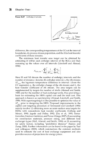
FIGURE 4.27 Enthalpy intervals. T
Enthalpy interval
1 q stream
= ·
A min
ΔT LM streams h stream
H
difference, the corresponding temperatures of the CCs at the interval
boundaries, its process stream population, and the film heat transfer
coefficients of those streams.
The minimum heat transfer area target can be obtained by
estimating it within each enthalpy interval of the BCCs and then
summing up the values over all intervals (Linnhoff and Ahmad,
1990):
HEN,min ¦ EI ª 1 ¦ NS q º , si
A « »
i 1 T LM,i s « 1 h , s i » ¬ ¼
Here EI and NS denote the number of enthalpy intervals and the
number of streams; i denotes ith enthalpy interval; s, the sth stream;
ΔT , the log-mean temperature difference in interval i (from the
LM,i
CC segments); q , the enthalpy change of the sth stream; and h , the
s s
heat transfer coefficient of sth stream. The area targets can be
supplemented by targets for number of shells (Ahmad and Smith,
1989) and for the number of heat exchanger units, thus providing a
basis for estimating the HEN capital cost and the total cost. This
approach is known as supertargeting (Ahmad, Linnhoff, and Smith,
1989). With supertargeting it is also possible to optimize the value of
ΔT prior to designing the HEN. Proposed improvements to the
min
capital cost targeting procedure of Townsend and Linnhoff (1984)
mainly involve: (1) obtaining more accurate surface area targets for
HENs with nonuniform heat transfer coefficients (Colberg and
Morari, 1990; Jegede and Polley, 1992; Zhu et al., 1995; Serna-
González, Jiménez-Gutiérrez, and Ponce-Ortega, 2007); (2) accounting
for construction materials, pressure rating, and different heat
exchanger types (Hall, Ahmad, and Smith, 1990); or (3) accounting
for safety factors, including “prohibitive distance” (Santos and
Zemp, 2000). Further information can be found in the paper by Taal
and colleagues (2003), which summarizes the common methods
used to estimate the cost of heat exchange equipment and also
provides sources of projections for energy prices.