
Page 180 - The Geological Interpretation of Well Logs
P. 180
~ THE GEOLOGICAL INTERPRETATION OF WELL LOGS -
orientation and palaeocurrent directions. Indeed the dip- dipmeter. /t will not be mentioned again let alone used.
meter is the only standard tool that can supply internal In this chapter, a strong bias will be put on the author’s
reservoir orientation information (image logs are not yet own views on dipmeter interpretation. It will be shown
standard, Chapter 13). how processing and interpretation interact and how out-
Prior 10 1967, a dipmeter too] could be expected to crop models can (and must) help interpretation. Dipmeter
provide one dip and azimuth per 2 m. Between 1967 and logs have a great potential which is only even now being
1984 this increased to 3-4 dips per metre: an eight-fold slowly realised.
increase. But moder tools can provide 40 times more Many of the ideas in the chapter owe a great deal to the
information than the original tools, that is up to 20 dips work of colleagues.
per metre: this means that there may be 20,000 individual
dip points measured aver 1000 m of logged open hole.
12.2 Dipmeter tools
This is a huge mass of data to interpret — and understand-
ably discourages and confuses most geologists. Dip is a Generalities
familiar geological concept and yet the data from the As indicated, the dipmeter tool measures dip by com-
dipmeter are unfamiliar. Clearly, this is a fundamental paring the displacements of microresistivity curves from
problem that must be tackled, opposing sides of the borehole wall (Figure (2.1).
Typically four pads are used, but tools exist with 3, 4, and
About this chapter
6 pads (three being the minimum number of points to
In the past (and even now), too many expensive dipmeter
define a planar surface) (Table 12.2). Moreover, although
logs have simply been put in a geologist’s drawer and
a single electrode on each pad is usual, the SHDT of
forgotten about. The high sampling rate of the raw dip-
Schlumberger has two on each pad (Figure | 2.5).
meter data has meant that in the past it was not integrated
Since the electrodes of the dipmeter tools register
with the other open hole logs in computer software. Also,
resistivity or conductivity, it is necessary for the borehole
that it needs processing and that its presentation is
Taud to be water based, allowing an electrical contact
unique, add more barriers. However, the dipmeter has and
between the tool and the formation. In oil based muds
is still suffering from poor credibility, not because of tool
this is not possible, and specialist tools using induction
design or reliability, or even processing — all excellent,
principles are run (Table 12.2). Alternatively, in some
but very poor interpretation.
cases, a compromise in oi] based muds is to use a stan-
Historically, dipmeter interpretation has been based on
dard resistivity dipmeter tool with ‘scratcher blades’,
the recognition of dip patterns. Three patterns are stand-
upstanding blade-like electrodes attached to the pads to
ard: red = decreasing dip upwards, blue = increasing dip
give a direct contact with the formation. The results using
upwards and green = constant dip (Gilreath et al., 1969).
this configuration are variable.
These patterns are given meaning: blue = foreset beds,
red = channel fill, green = structural dip. The associa- Tool mechanics
tions between the dip patterns and directional features The standard four arm dipmeter tool has four pads held at
have been expanded and enshrined since their original 90°, generally configured as two pairs, so that opposite
inception. The technique being that if a blue pattern or a pads move the same amount and the tool is automatically
red pattern can be identified, then an interpretation is centred (Figure 12.2). The arms can be so engineered that
assured. This methodology has been misrepresented over as hole size varies, the pad pairs move in a plane normal
the years and has blocked creative thinking about the to the tool axis but they generally move in a shallow arc
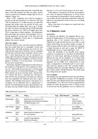
Table 12.2 Dipmeter logging tools.
Company Tool Names Pads Electrodes/pad Comments
Schlumberger HDT High Resolution Dipmeter Tool 4 1 older tool
SHDT Stratigraphic High Resolution Dipmeter 4 2 2.5mm samples
OBDT Oil Based Dipmeter Tool 4 ] oil base mud tool
Atlas Wireline Diplog Diplog 4 ! 5mm samples
HDIP Hexdip Log 6 I independent arms
Halliburton HEDT High Resolution Dipmeter Tool 4 I
SED Six Arm Dipmeter 6 1 independent arms
BPB PSD Precision Strata Dipmeter 341 10,5 or 2mm
MBD MultiButton Dipmeter 4 3 samples
170