
Page 181 - The Geological Interpretation of Well Logs
P. 181
- THE DIPMETER -
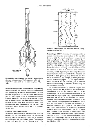
resistivity increases
—ie-
PAD 1 PAD2 PAD3 Pada
2730m—
J
2732m—
2734m
-
—
Figure 12.3 Raw dipmeter data from a Western Atlas Diplog,
sampled every 5mm (0.2").
Schlumberger SHDT dipmeter, for example, emits a
current from the entire lower section of the tool (the
Emex current}. The pads themselves are conductive but
only a small part of the overall current actually flows
through the measuring button electrodes, the major part
being used to focus the current from the buttons. Buttons,
pads and sonde body are kept at the same potential, so
the formation in front of it. Since the Emex current is
microrasistivity that button current will vary with the conductivity of
elactrode constantly varied, depending on the average formation
resistivity, button resistivity (conductivity) variations are
recorded in both generally high resistivity and low
resistivity formations. For example, in both hydrocarbon
Figure 12.2 A typical dipmeter too]: the HDT (high resolution
and salt water zones (Figure 12.4). The dipmeter micro-
dipmeter) of Schlumberger. The four arms are at 90° and
acquire four, micro-resistivity curves (modified from Bell, resistivity curves do not, therefore, give a standard
1990). resistivity: this can only be calculated by accounting for
the base current variations.
The dipmeter microresistivity curves are sampled very
and in six arm dipmeters, each arm moves independently
densely, every 5 mm (64 per foot) in the Western Atlas
and also in an arc. The pads are held against the borehole
Diplog and at twice this rate, every 2.5 mm 0.1") in the
wall hydraulically. In deviated boreholes this is a difficul-
Schlumberger SHDT, as oposed to the usual 15 cm (6") in
ty as the weight of the tool presses on the down-directed
other open hole logs (Figure 12.6). Dipmeter microresis-
pad and the top pad ‘floats’ or becomes disconnected
tivity data are handled in the so-called ‘fast channel’
from the formation. The weight of the tool on the pads
while the navigation data and calipers are handled in the
may be reduced using a flexi-joint and stand-offs (guards
‘slow channels’. The high dipmeter curve sampling rate is
to keep the tool away from the borehole wall). Tools
associated with very small pad electrode, or button (i.e.
can function in holes from about 20° to 6" (50 cm-15 cm)
small electrode) size, in the region of 1 cm, so that fea-
in diameter but are best in holes in the 12°-8" (30 cm—
tures as small as ] cm—2 cm (0.4"-0.8") are registered and
20 cm) range.
depth of penetration varies around 2 cm (0.9") (which
Resistivity curve characteristics must be added to the hole size to calculate dip). The
A dipmeter tool measures a microresistivity curve (or SHDT for example, has two electrodes | cm in diameter
curves) from each pad (Figure 12.3}. The essential for 3 em apart (Figure 12.5). The microresistivity pads them-
these curves is to register small variations in resistivity selves vary between tools but tend to be short and wide
or conductivity, and not absolute values. Consequently, (5-6 cm) to maximise formation contact and avoid stick-
a tool will typically use a ‘floating zero’. The ing (Bigelow, 1985).
17)