
Page 287 - The Handbook for Quality Management a Complete Guide to Operational Excellence
P. 287
274 C o n t i n u o u s I m p r o v e m e n t D e f i n e S t a g e 275
Event #1
Actual activity that
occurs between
event #1 and event #2
Event #2
Event #1
Dummy activity: Event #1
preceeds event #2, but no
activity occurs between them
Event #2
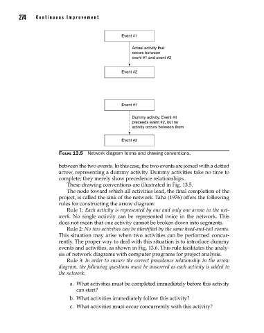
Figure 13.5 Network diagram terms and drawing conventions.
between the two events. In this case, the two events are joined with a dotted
arrow, representing a dummy activity. Dummy activities take no time to
complete; they merely show precedence relationships.
These drawing conventions are illustrated in Fig. 13.5.
The node toward which all activities lead, the final completion of the
project, is called the sink of the network. Taha (1976) offers the following
rules for constructing the arrow diagram:
Rule 1: Each activity is represented by one and only one arrow in the net-
work. No single activity can be represented twice in the network. This
does not mean that one activity cannot be broken down into segments.
Rule 2: No two activities can be identified by the same head-and-tail events.
This situation may arise when two activities can be performed concur
rently. The proper way to deal with this situation is to introduce dummy
events and activities, as shown in Fig. 13.6. This rule facilitates the analy
sis of network diagrams with computer programs for project analysis.
Rule 3: In order to ensure the correct precedence relationship in the arrow
diagram, the following questions must be answered as each activity is added to
the network:
a. What activities must be completed immediately before this activity
can start?
b. What activities immediately follow this activity?
c. What activities must occur concurrently with this activity?
13_Pyzdek_Ch13_p265-292.indd 274 11/9/12 5:14 PM