Page 825 - The Mechatronics Handbook
P. 825

066_Frame_C26  Page 10  Wednesday, January 9, 2002  1:59 PM


                                                                 4
                                                                    3
                                                                       2
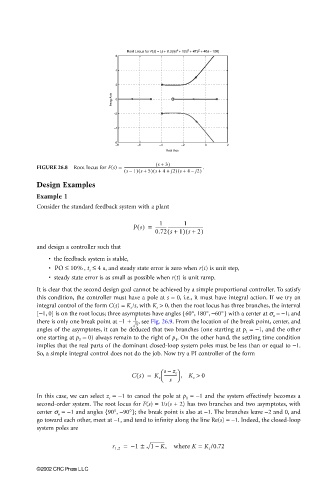
                                                  Root Locus for F(s) = (s + 0.3)/(s  + 12s  + 47s  + 40s − 100)
                                              6
                                              4
                                              2
                                             Imag Axis  0


                                              −2
                                              −4

                                              −6
                                              −8     −6    −4     −2     0      2
                                                             Real Axis
                                                          ( s +  3)
                       FIGURE 26.8  Root locus for F(s) = ---------------------------------------------------------------------------------------  .
                                                 ( s –  1) s +  5) s ++(  4  j2) s +  4 –  j2)
                                                     (
                                                                 (
                       Design Examples
                       Example 1
                       Consider the standard feedback system with a plant

                                                           1
                                                                   1
                                                    Ps() =  ------------------------------------------
                                                          0.72 s +  1) s + 2)
                                                                   (
                                                              (
                       and design a controller such that
                          • the feedback system is stable,
                          • PO ≤  10% , t s ≤  4 s , and steady state error is zero when r(t) is unit step,
                          • steady state error is as small as possible when r(t) is unit ramp.
                       It is clear that the second design goal cannot be achieved by a simple proportional controller. To satisfy
                       this condition, the controller must have a pole at s = 0, i.e., it must have integral action. If we try an
                       integral control of the form C(s) = K c /s, with K c  > 0, then the root locus has three branches, the interval
                       [−1, 0] is on the root locus; three asymptotes have angles {60°, 180°, −60°} with a center at s a  = −1; and
                                                    1
                       there is only one break point at 1 +–  ------- , see Fig. 26.9. From the location of the break point, center, and
                                                    3
                       angles of the asymptotes, it can be deduced that two branches (one starting at p 1  = −1, and the other
                       one starting at p 3  = 0) always remain to the right of p 1 . On the other hand, the settling time condition
                       implies that the real parts of the dominant closed-loop system poles must be less than or equal to −1.
                       So, a simple integral control does not do the job. Now try a PI controller of the form

                                                              –
                                                             ----------- , K c >
                                                   Cs() =  K c   sz c  0
                                                              s 
                       In this case, we can select z c  = −1 to cancel the pole at p 1  = −1 and the system effectively becomes a
                       second-order system. The root locus for F(s) = 1/s(s + 2) has two branches and two asymptotes, with
                       center σ a  = −1 and angles {90°, −90°}; the break point is also at −1. The branches leave −2 and 0, and
                       go toward each other, meet at −1, and tend to infinity along the line Re(s) = −1. Indeed, the closed-loop
                       system poles are

                                             r 1,2 =  – 1 ±  1 K,  where K =  K c /0.72
                                                          –


                       ©2002 CRC Press LLC
   820   821   822   823   824   825   826   827   828   829   830