Page 829 - The Mechatronics Handbook
P. 829

066_Frame_C26  Page 14  Wednesday, January 9, 2002  1:59 PM


                                               4
                                               3
                                               2
                                               1
                                             Imag Axis  0
                                              −1
                                              −2
                                              −3
                                              −4
                                               −6  −5   −4  −3   −2   −1   0    1
                                                             Real Axis

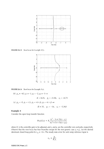
                       FIGURE 26.13  Root locus for Example 3(b).

                                               6

                                               4
                                               2
                                             Imag Axis  0


                                              −2
                                              −4

                                              −6
                                              −16  −14  −12  −10  −8  −6  −4  −2  0  2
                                                             Real Axis

                       FIGURE 26.14  Root locus for Example 3(c).
                        (b) p m  = −0.5, p 1  = −1, p 2  = −2, p 3  = −3 ⇒

                                               K = 8.25,  p  = −5.50,  z  = −0.73
                                                                     c
                                                          c
                         (c) p m  = −5, p 1  = −11, p 2  = −4 + j1, p 3  = −4 − j1 ⇒
                                                K = 35,  p  = −14,  z  = −5.343
                                                          c
                                                                   c
                       Example 4
                       Consider the open-loop transfer function

                                                             ( s – 3s + 3) sz c )
                                                                      (
                                                              2
                                                                        –
                                                P s()Cs() =  K c -------------------------------------------------
                                                                       (
                                                            ss +(  2  3s + 3) sp c )
                                                                         –
                       where K c  is the controller gain to be adjusted, and z c  and p c  are the controller zero and pole, respectively.
                       Observe that the root locus has four branches except for the non-generic case z c  = p c . Let the desired
                       dominant closed-loop poles be r 1,2  = −0.4. The steady state error for unit ramp reference input is
                                                          e ss =  ---------
                                                                p c
                                                               K c z c

                       ©2002 CRC Press LLC
   824   825   826   827   828   829   830   831   832   833   834