Page 827 - The Mechatronics Handbook
P. 827

066_Frame_C26  Page 12  Wednesday, January 9, 2002  1:59 PM


                                              10
                                               8
                                               6
                                               4
                                               2
                                             Imag Axis  0
                                              −2
                                              −4
                                              −6
                                              −8
                                              −10
                                                −12  −10  −8  −6  −4  −2  0  2  4
                                                              Real Axis

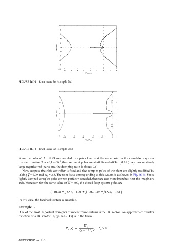
                       FIGURE 26.10  Root locus for Example 2(a).


                                              4
                                              3
                                              2
                                              1
                                             Imag Axis  0

                                              −1
                                              −2
                                              −3
                                              −4
                                                 −10  −8    −6    −4   −2    0
                                                              Real Axis
                       FIGURE 26.11  Root locus for Example 2(b).


                       Since the poles −0.2 ± j1.99 are canceled by a pair of zeros at the same point in the closed-loop system
                                              −1
                       transfer function T = G(1 + G) , the dominant poles are at −0.56 and −0.94 ± j1.61 (they have relatively
                       large negative real parts and the damping ratio is about 0.5).
                         Now, suppose that this controller is fixed and the complex poles of the plant are slightly modified by
                       taking ζ = 0.09 and ω 1  = 2.2. The root locus corresponding to this system is as shown in Fig. 26.11. Since
                       lightly damped complex poles are not perfectly canceled, there are two more branches near the imaginary
                       axis. Moreover, for the same value of K = 600, the closed-loop system poles are

                                                ±
                                                            ±
                                         { – 10.78  j2.57, 1.21  j1.86, 0.05 ± j1.93, 0.51}
                                                       –
                                                                              –
                       In this case, the feedback system is unstable.
                       Example 3
                       One of the most important examples of mechatronic systems is the DC motor.  An approximate transfer
                       function of a DC motor [8, pp. 141–143] is in the form


                                                             K m
                                                  P m s() =  --------------------------,  t m >  0
                                                          (
                                                          ss +  1/t m )
                       ©2002 CRC Press LLC
   822   823   824   825   826   827   828   829   830   831   832