
Page 65 - Vibrational Spectroscopic Imaging for Biomedical Applications
P. 65
Algal Cells, Cartilage, and IRENI 41
membranes. The bottom silicon wafer in contrast to the top wafer has
two additional through holes (diameter 1.5 mm) via which the liquid
enters the flow chamber volume. The bottom wafer is seated on a
®
thin, flat silicone or Viton seal that has two holes at the same posi-
®
tions. For compliance, a thin Teflon washer is placed between the lid
and the top silicon wafer. The lid is tightened to the base with the
help of six screws sealing the flow chamber.
The liquid medium enters the chamber volume through a metal tube
equipped with a luer lock, through an L-shaped channel in the base, the
bottom seal, and the bottom silicon wafer including the diamond film (see
blue arrows in Fig. 2.9). After flowing through the chamber volume, it exits
through the hole on the opposite side of the chamber. We use a syringe-
based push/pull pump to drive the liquid through the chamber. For the
algae experiments we chose to run the pump at a flow rate of 10 μL/min,
which corresponds roughly to one chamber volume per minute.
The diameter of the silicon wafers is chosen to be compatible with
34
conventional windows from PIKE Technologies which permits to use
their line of round spacers with a thickness down to 15 μm. The silicon
wafer thickness of 0.5 mm, on the other hand, makes it possible to use
high-end microscope objectives above the flow chamber with high
numerical aperture (for transmission and reflection setups). These
objectives typically have a short working distance down to the sub-
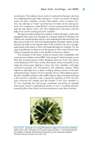
millimeter range. Figure 2.10, for example, shows a Micrasterias alga in
the flow chamber imaged with visible light in high resolution through
a 60× refractive objective with a numerical aperture of 0.70. The dis-
tance between the sample and the bottom of the flow chamber is
5.7 mm requiring the microscope condenser (assuming an upright
microscope setup in transmission mode) to have a working distance
exceeding this value. Most common condensers meet this condition.
FIGURE 2.10 Example of a living Micrasterias algal cell in the fl ow chamber
taken with a 60× refractive microscope objective (NA = 0.70) illustrating the
low degree of optical aberrations introduced by the diamond windows.
(Printed with permission from Ref. 18.)