
Page 315 - Water and wastewater engineering
P. 315
7-32 WATER AND WASTEWATER ENGINEERING
TABLE 7-4
Representative dimensions for upflow solids contact basin
Cone dimensions, m
Nominal Column Motor Number
a
Nominal SWD, Nominal Separation diameter, power, of
diameter, m m volume, m 3 h r 1 r 2 zone area, m 2 m kW weirs
6 3.7 109 2.5 3.8 1.2 25 0.6 0.5 8
9 4.3 288 3.1 5.3 1.5 60 1 1.5 8
12 4.8 580 3.6 6.5 2 100 1.3 2 8
15 5.3 970 4.1 7.5 2.7 160 1.7 3.5 8
18 5.5 1500 4.3 8.5 3.3 230 2 5.5 10
21 5.6 2140 4.4 9.5 4.2 300 2.3 7.5 10
24 5.8 2850 4.6 10 5 390 2.6 10 10
27 5.9 3730 4.7 10.5 6 480 3 15 10
30 6 4760 4.8 11.5 6.8 590 3.2 15 11
a
SWD side water depth. This depth is measured at the wall of the basin.
Weirs extend radially from the column to wall of the basin. Both sides are used in evaluating weir length.
Note: These basins are representative but do not represent actual choices. Actual manufacturer’s data must be used for real-world design.
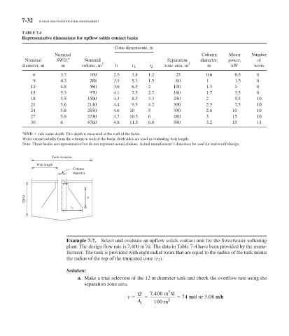
Tank diameter
Weir length
Column
diameter
r 2
SWD h
r 1
Example 7-7. Select and evaluate an upflow solids contact unit for the Sweetwater softening
3
plant. The design flow rate is 7,400 m /d. The data in Table 7-4 have been provided by the manu-
facturer. The tank is provided with eight radial weirs that are equal to the radius of the tank minus
the radius of the top of the truncated cone ( r 2 ).
Solution:
a. Make a trial selection of the 12 m diameter tank and check the overflow rate using the
separation zone area.
3
,
Q 7 400 m /d
v 74 m/d or 3 08 m/h
.
A 2
s 100 m