
Page 194 - A Comprehensive Guide to Solar Energy Systems
P. 194
196 A COmPrehenSIVe GUIDe TO SOlAr enerGy SySTemS
FIGURE 9.14 The selective emitter in trenches prepared by a laser ablation.
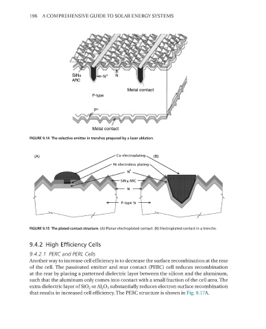
FIGURE 9.15 The plated contact structure. (A) Planar electroplated contact. (B) Electroplated contact in a trenche.
9.4.2 High Efficiency Cells
9.4.2.1 PERC and PERL Cells
Another way to increase cell efficiency is to decrease the surface recombination at the rear
of the cell. The passivated emitter and rear contact (PerC) cell reduces recombination
at the rear by placing a patterned dielectric layer between the silicon and the aluminum,
such that the aluminum only comes into contact with a small fraction of the cell area. The
extra dielectric layer of SiO 2 or Al 2 O 3 substantially reduces electron surface recombination
that results in increased cell efficiency. The PerC structure is shown in Fig. 9.17A.