
Page 338 - Acquisition and Processing of Marine Seismic Data
P. 338
6.3 SPIKING DECONVOLUTION 329
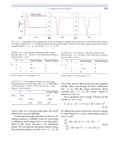
FIG. 6.17 Comparison of the performance of inverse filtering in spiking deconvolution for a maximum phase wavelet.
(A) Input wavelet w(t) ¼ ( 1, 2) with the desired zero lag spike output, and its inverse filter outputs using deconvolution
operators (B) h(t) ¼ ( 1, 2, 4), (C) h(t) ¼ ( 1, 2, 4, 8).
TABLE 6.6 Convolution of Minimum Phase Input TABLE 6.8 Convolution of Maximum Phase Input
Wavelet w(t) ¼ (2, 1) with a Two-Term Deconvolution Wavelet w(t) ¼ ( 1, 2) with a Two-Term Deconvolution
Operator h(t) ¼ (a, b) Operator h(t) ¼ (a, b)
2 21 Actual Output Desired Output
21 2 Actual Output Desired Output
b a 2a 1 b a a 1
b a 2b a 0 b a b+2a 0
b a b 0 b a 2b 0
Desired output is a zero-lag spike (1, 0, 0). Desired output is a zero-lag spike (1, 0, 0).
TABLE 6.7 Deconvolution Output by Convolving
Minimum Phase Input Wavelet w(t) ¼ (2, 1) With Filter which the inverse filter produces unacceptable
Coefficients h(t) ¼ (10/21, 4/21) Obtained by a Least results. After convolving the filter coefficients
Squares Approximation
h(t) ¼ (a, b) with the input maximum phase
wavelet w(t) ¼ ( 1, 2), the actual output is
2 21 Actual Output
shown in Table 6.8.
4/21 10/21 0.95
The cumulative error energy E based on the
4/21 10/21 0.095 results in Table 6.8 is
4/21 10/21 0.19 2 2 2
ð
½
E ¼ aÞ 1 + b +2að½ Þ 0 +2bðÞ 0
½
(6.15)
much closer to a zero-lag spike than the result By taking the partial derivatives of error energy
obtained by inverse filtering. E with respect to a and b, and setting them to
A least-squares approximation in inverse fil- zero, we get
tering produces a suitable result in converting ∂E
a minimum phase input into a zero-lag spike. ¼ 10a 4b +2 ¼ 0 ) 5a 2b ¼ 1
∂a
What if the input wavelet is not minimum (6.16)
phase? We can perform the same analysis using ∂E ¼ 10b 4a ¼ 0 ) 2a +5b ¼ 0
the maximum phase wavelet w(t) ¼ ( 1, 2) on ∂b