
Page 342 - Acquisition and Processing of Marine Seismic Data
P. 342
6.3 SPIKING DECONVOLUTION 333
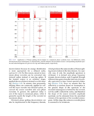
FIG. 6.20 Application of Wiener spiking deconvolution to a minimum phase synthetic trace. (A) Reflectivity series,
(B) minimum phase seismogram, (C) deterministic, and (D) statistical deconvolution results. Corresponding amplitude spec-
tra and autocorrelograms are given in the top and bottom panels, respectively.
deconvolution because its energy distribution which produces the same results as Wiener spik-
is more appropriate for a delayed spike, ing deconvolution in the time domain. As a spe-
such as (0, 1, 0). For this reason, mixed or max- cific case, if only the amplitude spectrum is
imum phase wavelets can be converted into whitened, it is termed zero phase frequency
delayed spikes instead of zero-lag spikes. If domain deconvolution, and if applied through
the desired output is an arbitrary shape, different time gates along the time axis, it is actu-
applied deconvolution is termed wavelet shap- ally equivalent to time variant spectral whiten-
ing (Section 6.8). In seismic data processing, ing (Section 12.4). Since we assume that the
shaping filters are commonly applied to con- reflectivity is random, based on Assumption 6,
vert the input wavelet into delayed spikes, or the general shape of the spectrum of the
convert the source wavelets into zero phase recorded seismogram is formed by the wavelet,
wavelets. In general, the optimum delay is not the earth’s reflectivity series, and therefore
zero if the input is minimum phase, while it the shape of the source wavelet’s amplitude
generally equals the length of the wavelet for spectrum can be estimated from the smoothed
maximum phase. version of the spectrum of the recorded seismo-
Minimum phase spiking deconvolution can gram. At this stage, the unknown wavelet phase
also be implemented in the frequency domain, is assumed to be minimum.