
Page 339 - Acquisition and Processing of Marine Seismic Data
P. 339
330 6. DECONVOLUTION
Rearranging Eq. (6.16) into a matrix form, and approximation for minimum and maximum
solving it for filter coefficients a and b, we obtain phase wavelets are compared in Fig. 6.18.
As a result, the spiking deconvolution opera-
5 2 a 1
2 3 2 3 2 3
tor is exactly the inverse of the input source
4 5 4 5 ¼ 4 5 wavelet. If the wavelet is of minimum phase
2 5 b 0 (6.17)
and its energy is front-loaded, then it has a stable
5 2
a ¼ and b ¼ inverse. Its inverse is also minimum phase
21 21 because its coefficients constitute a convergent
Convolving these coefficients with the input series so that the energy of the wavelet inverse
wavelet w(t) ¼ ( 1, 2) to obtain the deconvolved is also front-loaded. This inverse is used as a sta-
output, we obtain the results in Table 6.9. ble filter operator for the deconvolution process.
Although the deconvolved output is closer to a On the other hand, if the wavelet is of maximum
spike as compared to the inverse filter output or mixed phase, then it has an unstable inverse
for the maximum phase wavelet, it does which is not favorable to use as a spiking decon-
not match the desired deconvolution output volution operator.
because of the violation of Assumption 5. The
results of the deconvolution with a least-squares
6.3.3 Optimum Wiener Filters
Recalling Eq. (6.14) to convert minimum
TABLE 6.9 Deconvolution Output by Convolving
Maximum Phase Input Wavelet w(t) ¼ ( 1, 2) With phase input wavelet w(t) ¼ (2, 1) into a zero-
Filter Coefficients h(t) ¼ ( 5/21, 2/21) Obtained by a lag spike (1, 0, 0), we observe that the lefthand
Least-Squares Approximation side of Eq. (6.14) consists of autocorrelation
of the input wavelet (Table 6.10), while the
21 2 Actual Output
righthand side is composed of cross-correlation
2/21 5/21 0.238 of the desired output and input wavelet
2/21 5/21 0.38 (Table 6.11).
For an operator consisting of n terms, we
2/21 5/21 0.19
get the following general equation system for
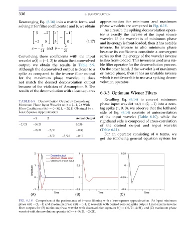
FIG. 6.18 Comparison of the performance of inverse filtering with a least-squares approximation. (A) Input minimum
phase w(t) ¼ (2, 1) and maximum phase w(t) ¼ ( 1, 2) wavelets with desired zero-lag spike output. Least-squares inverse
filter outputs for (B) minimum phase wavelet with deconvolution operator h(t) ¼ (10/21, 4/21), and (C) maximum phase
wavelet with deconvolution operator h(t) ¼ ( 5/21, 2/21).