
Page 311 - Biomedical Engineering and Design Handbook Volume 2, Applications
P. 311
THE PRINCIPLES OF X-RAY COMPUTED TOMOGRAPHY 289
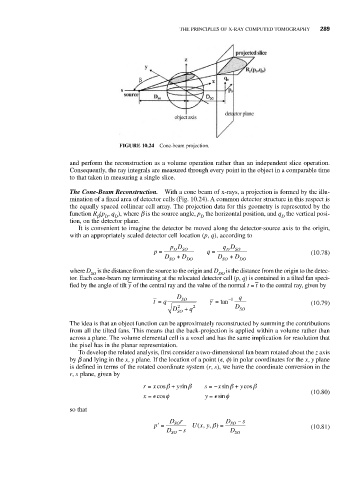
FIGURE 10.24 Cone-beam projection.
and perform the reconstruction as a volume operation rather than an independent slice operation.
Consequently, the ray integrals are measured through every point in the object in a comparable time
to that taken in measuring a single slice.
The Cone-Beam Reconstruction. With a cone beam of x-rays, a projection is formed by the illu-
mination of a fixed area of detector cells (Fig. 10.24). A common detector structure in this respect is
the equally spaced collinear cell array. The projection data for this geometry is represented by the
function R (p , q ), where b is the source angle, p the horizontal position, and q the vertical posi-
D
b
D
D
D
tion, on the detector plane.
It is convenient to imagine the detector be moved along the detector-source axis to the origin,
with an appropriately scaled detector cell location (p, q), according to
pD qD
p = D SO q = D SO (10.78)
D + D D + D
SO DO SO DO
where D is the distance from the source to the origin and D is the distance from the origin to the detec-
SO DO
tor. Each cone-beam ray terminating at the relocated detector cell (p, q) is contained in a tilted fan speci-
–
–
fied by the angle of tilt y of the central ray and the value of the normal t = t to the central ray, given by
D q
t = q SO γ = tan −1 (10.79)
D 2 + q 2 D SO
SO
The idea is that an object function can be approximately reconstructed by summing the contributions
from all the tilted fans. This means that the back-projection is applied within a volume rather than
across a plane. The volume elemental cell is a voxel and has the same implication for resolution that
the pixel has in the planar representation.
To develop the related analysis, first consider a two-dimensional fan beam rotated about the z axis
by b and lying in the x, y plane. If the location of a point ( , f) in polar coordinates for the x, y plane
is defined in terms of the rotated coordinate system (r, s), we have the coordinate conversion in the
r, s plane, given by
r = cosβ + ysinβ s = − sinβ + ycosβ
x
x
(10.80)
x = cosφ y = sinφ
so that
Dr D − s
p ′ = SO Ux y, )β = SO (10.81)
(,
D SO − s D SO