
Page 186 - Boiler plant and distribution system optimization manual
P. 186
Over 100 Ways to Improve Efficiency 171
It can also be used on boilers for heating process 4. AIR PREHEATER
or domestic hot water. A heat exchanger is in-
stalled in the stack with its own pump and regu- Cost
lating valve and is basically an additional heat ex- Moderate to High
change surface for the heating unit. The flue gas
temperature can be controlled by regulating the Potential Savings
flow of water through the heat reclaimer. Many Moderate
of the older hydronic boilers have high stack tem-
peratures and high excess air levels, making this Description
option very attractive. Another means to recover the wasted ener-
gy resource in the flue gas is the air preheater,
Advantages/Disadvantages (Figure 10.69) which is used to heat the incoming
Design and installation costs on the smaller combustion air. This is an excellent way to cap-
units may be hard to justify, otherwise they are ture energy which would otherwise be lost and
relatively trouble free low cost units. The heat re- to put it back to work in the boiler. The rule of
claimer has two advantages, (a) it recovers waste thumb which applies to this type of heater is that
heat and (b) it lowers excess air on atmospheric you can expect a one percent efficiency increase
type boilers by cooling exhaust gasses creating for every 40 degrees that you can decrease the net
less furnace draw in both the on and off condi- stack temperature (outlet stack temperature mi-
tion.
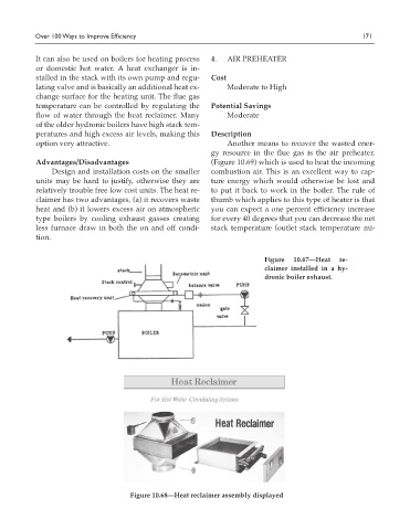
Figure 10.67—Heat re-
claimer installed in a hy-
dronic boiler exhaust.
Figure 10.68—Heat reclaimer assembly displayed