
Page 426 - DSP Integrated Circuits
P. 426
9.7 Building Large DSP Systems 411
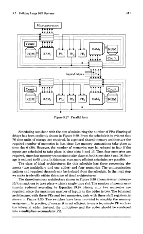
Figure 9.27 Parallel form
Scheduling was done with the aim of minimizing the number of PEs. Sharing of
delays has been explicitly shown in Figure 9.29. From the schedule it is evident that
76 time units of storage are required. In a general shared-memory architecture the
required number of memories is five, since five memory transactions take place at
time slot 0 (20). However, the number of memories may be reduced to four if the
inputs are scheduled to take place in time slots 5 and 13. Then four memories are
required, since four memory transactions take place at both time slots 8 and 16. Stor-
age is reduced to 68 units. In this case, even more efficient schedules are possible.
The class of ideal architectures for this schedule has three processing ele-
ments (two multipliers and one adder) and four memories. The communication
pattern and required channels can be deduced from the schedule. In the next step
we make trade-offs within this class of ideal architectures.
The shared-memory architecture shown in Figure 9.30 allows several memory-
PE transactions to take place within a single time slot. The number of memories is
thereby reduced according to Equation (9.9). Hence, only two memories are
required, since the maximum number of inputs to the adder is two. The balanced
architecture, with three PEs and two memories, each with three shift registers, is
shown in Figure 9.30. Two switches have been provided to simplify the memory
assignment. In practice, of course, it is not efficient to use a too simple PE such as
the bit-serial adder. Instead, the multipliers and the adder should be combined
into a multiplier—accumulator PE.