
Page 428 - DSP Integrated Circuits
P. 428
9.8 Interpolator, Cont. 413
Figure 9.30 Balanced architecture with three PEs and two memories
9.8 INTERPOLATOR, CONT.
The wave digital filter used for interpolation was scheduled in 6 time units,
using the adaptors as basic operations. Four PEs each with two inputs and two
outputs were needed. Hence, to support four PEs we need 2- 4 = 8 memories in
the ideal architecture. A single memory can support several PEs. The schedule
implies that 24 adaptor operations are executed per sample interval and each
adaptor operation requires two read and two write operations. Hence, a memory
with access rate
would be enough. It is possible to design such fast memories, but it is difficult.
Therefore we choose to use two memories working at only 76.8 MHz. Each memory
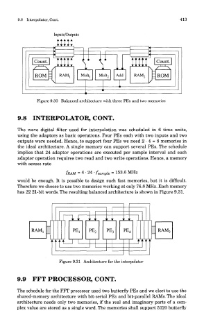
has 22 21-bit words. The resulting balanced architecture is shown in Figure 9.31.
Figure 9.31 Architecture for the interpolator
9.9 FFT PROCESSOR, CONT.
The schedule for the FFT processor used two butterfly PEs and we elect to use the
shared-memory architecture with bit-serial PEs and bit-parallel RAMs. The ideal
architecture needs only two memories, if the real and imaginary parts of a com-
plex value are stored as a single word. The memories shall support 5120 butterfly