
Page 433 - DSP Integrated Circuits
P. 433
418 Chapter 9 Synthesis of DSP Architectures
The first equation, Equation (9.15), describes the transformation from index
to butterfly in a stage. The second equation describes the remaining transforma-
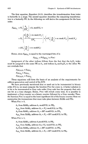
tion to a butterfly PE. In the following we will derive the assignment for the base
index
Hence, since SpF.ki is equal to the rearranged bits of ra
Assignment of the other indices follows from the fact that the kiN s index
must be assigned to the same PE as k\, and indices k% and k%N s to the other. We
can conclude that
These equations will form the basis of an analysis of the requirements f
address generation and control of the ICN.
We have previously mentioned that m need not to be incremented in bina
order. If it is, we must compute the function P(m) for every m. A better solution
to let m be incremented in Gray code order. Gray code has the property that on
one bit at a time changes. Hence, P(m) will switch every time. It is possible
implement a Gray counter as a binary counter followed by a Gray encoder. The
the function P(m) is equal to the least significant bit of the binary counter. Next \
summarize the transactions that must take place between RAMs and PEs.
When P(m) = 0,
k\ from RAMo; address k\ mod(M2), to PEo
kix from RAMi; address (&i + N s) mod(M2), to PEo
k 2 from RAMn address (ki + BF) mod(A//2), to PE!
&2N from RAM 0; address (&i + N s + BF) mod(M2), to PEx
S
WhenP(m)=l,
ki from RAMi; address &imod(M2), to PEi
&1AT from RAMo; address (k\+ N s) mod(7V72), to PEi
k 2 from RAM 0; address (ki+BF) mod(M2), to PE 0
&2AT from RAMi; address (&i + N s + BF) mod(JV72), to PE 0