
Page 440 - DSP Integrated Circuits
P. 440
9.10 DCT Processor, Cont. 425
9.10 DCT PROCESSOR, CONT.
It was determined in Chapter 7 that only two 1-D DCT processing elements are
required. Each PE requires 16 input values and delivers 16 output values. Accord-
ing to the schedule data are written into the memories in the first phase (16 time
units), while during the last phase data are read from the memories. Hence, from
a memory point of view, a 1-D DCT computation involves either a write or a read
operation. Thus, the ideal architecture, with two PEs, should have 2 • 16 = 32
memories. The schedule length of 34 time units implies an execution time for the
DCT PEs, including communication time and either a read or a write cycle, of
Hence, fps = 8.262 MHz. Using only one memory to support both PEs the
required access rate is
6
fRAM= 8-262 • 10 • 2 • 16 = 264.4 MHz
which is much too high. We therefore choose to use four memories, two per PE.
The required access rate becomes a more reasonable 66.1 MHz. Each memory has
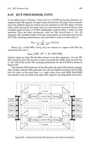
8 • 16 = 128 12-bit words. The resulting architecture for the 2-D DCT is shown in
Figure 9.38.
The external FIFOs feed one of the PEs while the other PE produces outputs.
After 16 time units the PEs exchange roles. The two RAMs should provide the PEs
with 16 values in bit-serial form—i.e., eight values from each RAM. Each RAM
has therefore been provided with eight shift registers (serial/parallel converters).
Figure 9.38 Architecture for the DCT processor with external memories