
Page 454 - DSP Integrated Circuits
P. 454
10.3 Sequential Networks 439
The second case is to choose N% fixed and optimize only A/I. If a NOR-NOR
structure is chosen for NI and A/2, the Boolean function should be written in POS
(products-of-sums) form. If, instead, a NAND-NAND structure is chosen, the
appropriate form is SOP (sum-of-products). Which of these two forms is the more
efficient depends on the properties of the Boolean functions to be implemented.
The third case, where both NI and A^ are optimized, occurs in the implemen-
tation of FSM (finite-state machines). Two-level logic functions with many com-
mon Boolean terms can be implemented effectively using PLAs (programmable
logic arrays). Boolean functions with many don't care input and output values are
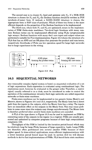
particularly suitable for PLA implementation. Figure 10.3 shows the structure of a
PLA that has an AND and an OR plane that generate the product and sum terms,
respectively. Drawbacks of PLAs are low operation speed for large logic networks
due to large capacitance in the wiring.
Figure 10.3 PLA
10.3 SEQUENTIAL NETWORKS
Any reasonably complex digital system is based on sequential evaluation of a set
of logic expressions. Each expression is evaluated using combinational logic. The
expressions must, however, be evaluated in the proper order. Therefore, a control
signal, usually referred to as a clock, must be introduced in order to control the
operation of the combinational circuitry. Such logic networks are called sequential
networks or finite-state machines.
Finite-state machines can be implemented in two generic forms, Mealy's and
Moore's, shown in Figures 10.4 and 10.5, respectively. The Mealy form has a direct
path from the inputs to the outputs, while the Moore form has a delay. The inputs
have an immediate effect on the outputs in the Mealy from. This may cause prob-
lems in some cases since the outputs may change asynchronously. The Moore form
is therefore preferred when several finite-state machines are cascaded.
A PLA of the type shown in Figure 10.3 can be used to implement an FSM by
connecting some of the outputs to the inputs via a register. FSMs are usually gen-
erated and optimized by computer programs because of their high computational
complexity [19].
Throughput of the FSM is limited by the iteration period bound which may
be relatively long for large PLAs, because of large capacitive loads. Large FSMs
are therefore often partitioned into several smaller FSMs because of their
higher speed. In time-critical applications, more efficient implementations with
a lower iteration period bound must be used. In section 10.6 we will discuss
methods to derive fast implementations of FSMs. PLA-based finite-state machines