
Page 455 - DSP Integrated Circuits
P. 455
440 Chapter 10 Digital Systems
Figure 10.4 Mealys form of FSM. Figure 10.5 Moores form of FSM
are often used to implement noncritical (time) functions. Fast FSMs are gener-
ally implemented using so-called random logic in which the critical paths have
been minimized.
10.4 STORAGE ELEMENTS
Flip-flop: The song on the other side of a hit record
A storage element is a device that can store a value applied to the input of the ele-
ment. The storage element is controlled by a clock signal that periodically changes
between logic 0 and logic 1. These two states are referred to as clock phases.
Depending on their behavior during these phases, storage elements are classed as
either latches or flip-flops.
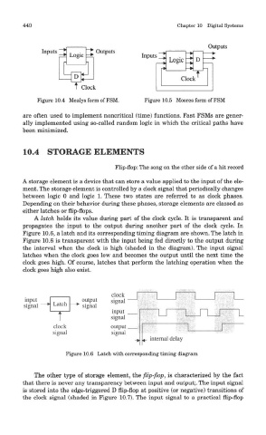
A latch holds its value during part of the clock cycle. It is transparent and
propagates the input to the output during another part of the clock cycle. In
Figure 10.6, a latch and its corresponding timing diagram are shown. The latch in
Figure 10.6 is transparent with the input being fed directly to the output during
the interval when the clock is high (shaded in the diagram). The input signal
latches when the clock goes low and becomes the output until the next time the
clock goes high. Of course, latches that perform the latching operation when the
clock goes high also exist.
Figure 10.6 Latch with corresponding timing diagram
The other type of storage element, the flip-flop, is characterized by the fact
that there is never any transparency between input and output;. The input signal
is stored into the edge-triggered D flip-flop at positive (or negative) transitions of
the clock signal (shaded in Figure 10.7). The input signal to a practical flip-flop