
Page 193 - Electrical Properties of Materials
P. 193
The transistor 175
αi e
r r
e c
C C
e c
r
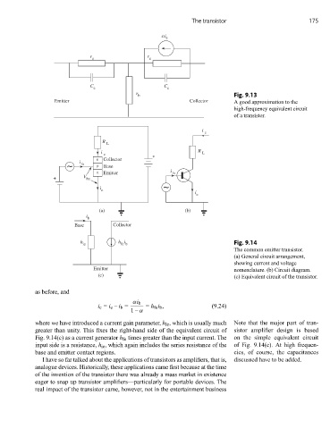
b Fig. 9.13
E m r e t t i C o t c e l l o r A good approximation to the
high-frequency equivalent circuit
of a transistor.
i
c
R
L
i R L
c +
n Collector
i
~ b p Base
n Emitter i b
+ V be
i ~
e
i
e
) a ( ) b (
i
b
Base Collector
h h i Fig. 9.14
ie fe b
The common emitter transistor.
(a) General circuit arrangement,
showing current and voltage
Emitter nomenclature. (b) Circuit diagram.
(c) (c) Equivalent circuit of the transistor.
as before, and
αi b
i c = i e – i b = = h fe i b , (9.24)
1– α
where we have introduced a current gain parameter, h fe , which is usually much Note that the major part of tran-
greater than unity. This fixes the right-hand side of the equivalent circuit of sistor amplifier design is based
Fig. 9.14(c) as a current generator h fe times greater than the input current. The on the simple equivalent circuit
input side is a resistance, h ie , which again includes the series resistance of the of Fig. 9.14(c). At high frequen-
base and emitter contact regions. cies, of course, the capacitances
I have so far talked about the applications of transistors as amplifiers, that is, discussed have to be added.
analogue devices. Historically, these applications came first because at the time
of the invention of the transistor there was already a mass market in existence
eager to snap up transistor amplifiers—particularly for portable devices. The
real impact of the transistor came, however, not in the entertainment business