
Page 169 - Embedded Microprocessor Systems Real World Design
P. 169
CPU
INTERRUPT INPUT
NMI
CONTROL SIGNAL
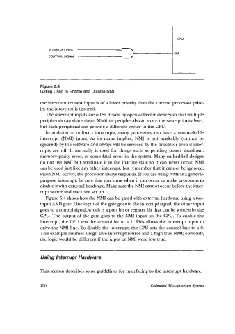
Figure 5.4
Gating Used to Enable and Disable NMI.
the interrupt request input is of a lower priority than the current processor prior-
ity, the interrupt is ignored.
The interrupt inputs are often driven by opencollector devices so that multiple
peripherals can share them. Multiple peripherals can share the same priority level,
but each peripheral can provide a different vector to the CPU.
In addition to ordinary interrupts, many processors also have a nonmaskable
interrupt (NMI) input. As its name implies, NMI is not maskable (cannot be
ignored) by the software and always will be serviced by the processor even if inter-
rupts are off. It normally is used for things such as pending power shutdown,
memory parity error, or some fatal error in the system. Many embedded designs
do not use NMI but terminate it in the inactive state so it can never occur. NMI
can be used just like any other interrupt, but remember that it cannot be ignored;
when NMI occurs, the processor always responds. If you are using NMI as a general-
purpose interrupt, be sure that you know when it can occur or make provisions to
disable it with external hardware. Make sure the NMI cannot occur before the inter-
rupt vector and stack are set up.
Figure 5.4 shows how the NMI can be gated with external hardware using a two-
input AND gate. One input of the gate goes to the interrupt signal; the other input
goes to a control signal, which is a port bit or register bit that can be written by the
CPU. The output of the gate goes to the NMI input on the CPU. To enable the
interrupt, the CPU sets the control bit to a 1. This allows the interrupt input to
drive the NMI line. To disable the interrupt, the CPU sets the control line to a 0.
This example assumes a high true interrupt source and a high true NMI; obviously,
the logic would be different if the input or NMI were low true.
Using Interrupt Hardware
This section describes some guidelines for interfacing to the interrupt hardware.
150 Embedded Microprocessor Systems