
Page 304 - Engineering Digital Design
P. 304
6.8 COMBINATIONAL SHIFTERS 275
generator module of Fig. 6.33 with an XOR gate and inverter as the output stage, hence an
EQV gate, as implied in Fig. 6.34.
The parity checking scheme illustrated in Fig. 6.34 is valid for the detection of a single
error in the 8-bit word. Actually, it is valid for any odd number of errors, but the probability
that three or more errors will occur in a given word is near zero. What a single-bit parity
checking system cannot do is detect an even number of errors (e.g., two errors). It is also true
that the error checking system of Fig. 6.34 cannot correct any single error it detects. To do
so would require detecting its location, which is no trivial task. To identify the location of an
error bit requires multiple parity detection units on the submodular level down on the bit
level, a significant cost in hardware. However, when this is done, an erroneous bit can be cor-
rected. Memory systems in modern computers have such single-error correction capability.
6.8 COMBINATIONAL SHIFTERS
Shifting or rotating of word bits to the right or left can be accomplished by using combina-
tional logic. Devices that can accomplish this are called combinational shifters, or barrel
shifters if their function is only to rotate word bits. Shifters are used for bit extraction op-
erations, transport, editing, data modification, and arithmetic manipulation, among other
applications.
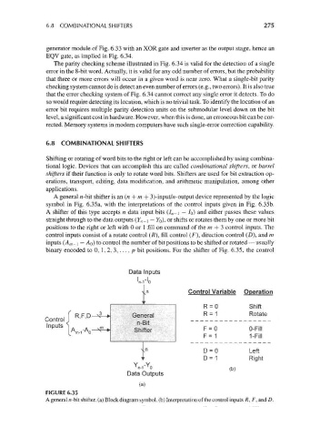
A general n-bit shifter is an (n + m + 3)-input/n-output device represented by the logic
symbol in Fig. 6.35a, with the interpretations of the control inputs given in Fig. 6.35b.
A shifter of this type accepts n data input bits (I n-\ — /o) and either passes these values
straight through to the data outputs (F, 7_i — YQ), or shifts or rotates them by one or more bit
positions to the right or left with 0 or 1 fill on command of the m + 3 control inputs. The
control inputs consist of a rotate control (/?), fill control (F), direction control (D), and m
inputs (A m _ i — AQ) to control the number of bit positions to be shifted or rotated — usually
binary encoded to 0, 1, 2, 3, ...,/ ? bit positions. For the shifter of Fig. 6.35, the control
Data Inputs
ln-r'o
Control Variable Operation
R = 0 Shift
,3 General R = 1 Rotate
' ' '
Control] R F D
n-Bit
ts
'"P" \A m ,-A n -^ Sh«er F = 0 0-Fill
F = 1 1-Fill
D = 0 Left
D = 1 Right
Y -Y
T
T
n-1 0 (b)
Data Outputs
(a)
FIGURE 6.35
A general «-bit shifter, (a) Block diagram symbol, (b) Interpretation of the control inputs R, F, and D.