
Page 305 - Engineering Digital Design
P. 305
276 CHAPTER 6 / NONARITHMETIC COMBINATIONAL LOGIC DEVICES
1 1 0 1 1 1 0 1
111 1 111 1
R = 0
F = 0
D = 0
Y Y Y Y
T 3 T 2 T 1 T 0
111 1
0 0 1 1 0 1
.j
0_ FilIbits / (b) Spill bits
1 1 0 1 1 1 0 1
1 1 1 I 111 1
1 !
'0
R = 3 2 '1 1 Jc R= 1
D= 1 D = 0
Y T 3 Y 2 Y 1 T Y < Y T 3 Y 2 Y 1 T Y 0
T
T
T
T
i r i i \ \\ \
1 1 1 0 0 1 1 1
(c) (d)
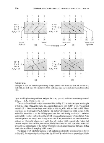
FIGURE 6.36
Examples of shift and rotation operations by using a general 4-bit shifter, (a) Shift left one bit (sll)
with 0-fill. (b) Shift right 2 bits (sr2) with 0-Fill. (c) Rotate right one bit (rrl). (d) Rotate left two bits
input word is given the positional weights RFDA m-\ • • • AQ and is sometimes represented
as Sk-\ • • • S\ SQ, where k = m + 3.
The control variable (R = 0) causes the shifter in Fig. 6.35 to shift the input word (right
or left) by p bits while, at the same time, causes Spill and 0- or 1-Fill by p bits. The control
variable (/? = !) rotates the input word (right or left) by p bits with no Spill or Fill. These
operations are illustrated in Fig. 6.36 for a 4-bit shifter with input word 1101. In Figs. 6.36a
and 6.36b, the shifter is set for shifting operations, first shift left by one bit (s€l) and then
shift right by two bits (sr2) with spill and 0-fill bits equal to the number of bits shifted. Note
that the spill bits are always lost. In Figs. 6.36c and 6.36d, the shifter is set for rotation with
settings for 1-bit right rotation (rrl) and 2-bits left rotation (r£2), respectively. Notice that
rotation requires that end bits, normally spilled (discarded) in a shift operation, be rotated
around to the opposite end of the shifter. The rotation mode could be called the barrel shifter
mode, the word barrel implying "shift around."
The design of a 4-bit shifter capable of left shifting or rotation by up to three bits is shown
in Fig. 6.37. To reduce the size of the table, the fill bit F is included as an entered variable in