
Page 310 - Engineering Digital Design
P. 310
6.10 INTRODUCTION TO VHDL DESCRIPTION OF COMBINATIONAL PRIMITIVES 281
level. Examples of the behavior level of representation are truth tables and algorithmic
descriptions. The structural level of representation typically includes various primitives
together with the interconnections required to make a circuit. The primitives covered in this
chapter include discrete gates, decoders, encoders, MUXs, comparators, parity generators,
and combinational shifters. Other primitives, including those associated with arithmetic
circuits, PLDs, and sequential circuits, will be considered in subsequent chapters.
Before illustrating the use of VHDL for some well known combinational primitives, it
will be helpful to review some assignment statements relevant to behavioral modeling. For
example,
a <=b;
is read as "a is assigned the value of b." As a second example,
Y <= 12 after 10 ns;
is interpreted as follows: "Y is assigned the value of 12 after 10 nanoseconds have elapsed."
In these two examples, "<=" is an assignment operator that assigns a value to a sig-
nal. Another assignment operator is the ":=" operator. It is used to assign a value to a
variable:
result := X; or delay := 4 ns;
Here, result and delay are variables and are assigned the values of X and 4 ns, respectively.
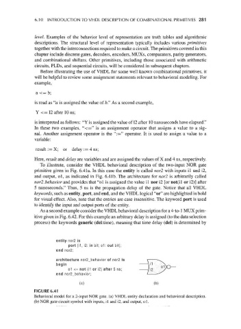
To illustrate, consider the VHDL behavioral description of the two-input NOR gate
primitive given in Fig. 6.4la. In this case the entity is called nor2 with inputs il and i2,
and output, ol, as indicated in Fig. 6.4Ib. The architecture for nor2 is arbitrarily called
nor2.behavior and provides that "ol is assigned the value il nor i2 [or not(il or i2)] after
5 nanoseconds." Thus, 5 ns is the propagation delay of the gate. Notice that all VHDL
keywords, such as entity, port, and end, and the VHDL logical "or" are highlighted in bold
for visual effect. Also, note that the entries are case insensitive. The keyword port is used
to identify the input and output ports of the entity.
As a second example consider the VHDL behavioral description for a 4-to-1 MUX prim-
itive given in Fig. 6.42. For this example an arbitrary delay is assigned (to the data selection
process) the keywords generic (del:time), meaning that time delay (del) is determined by
entity nor2 is
port (11, i2: in bit; o1: out bit);
end nor2;
architecture nor2_behavior of nor2 is
begin
o1 <= not (11 or i2) after 5 ns;
end nor2_behavior;
(a) (b)
FIGURE 6.41
Behavioral model for a 2-input NOR gate, (a) VHDL entity declaration and behavioral description,
(b) NOR gate circuit symbol with inputs, il and i2, and output, ol.