
Page 307 - Engineering Digital Design
P. 307
278 CHAPTER 6 / NONARITHMETIC COMBINATIONAL LOGIC DEVICES
Notice that in Fig. 6.38 the control variable D is missing, meaning that D = 0 for left
shifting. Had the variable D been included for left or right shifting/rotating, fourth-order
EV K-maps and 16-to-l MUXs would have to be used if the architecture of Fig. 6.38 were
to be retained. Also note that this shifter can be cascaded by connecting 7 3 (H) of one stage
to F(H) of the next most significant stage, etc.
6.9 STEERING LOGIC AND TRI-STATE GATE APPLICATIONS
Any of the combinational logic devices discussed to this point can be designed by using
transmission gates together with inverters. When this is done the devices are classified
as steering logic. A transmission gate lacks logic function capability by itself, but can be
configured with other transmission gates to steer the logic signals in a manner that carries out
a logic function. Inverters are necessarily included in most steering logic designs because
transmission gates are passive and noninverting, as explained in Section 3.5.
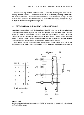
As a simple example, consider a 4-to-l MUX defined by the truth table in Fig. 6.39a.
This device can be implemented easily with CMOS transmission gates and inverters and at
AND plane
EN s, S o Y
0 X X --
1 0 0 i.
1 0 1 i,
1 1 0
'a
1 1 1 I
X = Irrelevant Input
(a)
S,(H) S 0(H)
(b)
FIGURE 6.39
Transmission gate implementation of the 4-to-l MUX. (a) Truth table, (b) Logic circuit with a tri-state
buffered/enabled output.