
Page 302 - Engineering Digital Design
P. 302
6.7 PARITY GENERATORS AND ERROR CHECKING SYSTEMS 273
6.7 PARITY GENERATORS AND ERROR CHECKING SYSTEMS
A parity bit can be appended to any word of n bits to generate an even or an odd number
of 1's (or O's). A combinational logic device that generates even or odd parity is called a
parity generator. A device that is used to detect even or odd parity is called aparity detector.
To understand the concept of parity generation and detection, consider the following 8-bit
words to which a ninth parity bit is appended as the LSB shown in brackets:
1 101010 1 [1]: Even parity generation — Odd parity detection
1 101010 1 [0]: Odd parity generation = Even parity detection
or
1 101000 1 [1]: Odd parity generation = Even parity detection
1 1 0 1 0 0 0 1 [0]: Even parity generation = Odd parity detection.
Thus, parity generation includes the parity bit in the count of 1's, whereas parity detection
excludes the parity bit in the count but uses the parity bit to identify the parity status (even
or odd) of the word. The parity bit may be appended either at the LSB position, as in the
examples just given, or at the MSB position.
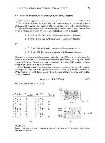
XOR gates can be combined to produce rc-bit parity circuits. As an example, consider
the design of a 4-bit even-parity generator module shown in Fig. 6.32. The second-order
EV K-maps in Fig. 6.32b follow directly from the truth table in Fig. 6.32a and yield the
output expression
P Even Gen = A®B@C®D, (6.24)
which is implemented in Fig. 6.32c.
AB CD p AB CD p
Even Gen Even Gen
000 0 0 100 0 1
000 1 1 100 1 0 Even Gen
001 0 1 101 0 0
001 1 0 101 1 1
010 0 1 110 0 0 B(H)
010 1 0 110 1 1
011 0 0 111 0 1
011 1 1 111 1 0 D(H)
(a) (c)
FIGURE 6.32
Design of the 4-bit even parity generator module, (a) Truth table, (b) EV K-map. (c) Logic circuit
according to Eq. (6.24).