
Page 303 - Engineering Digital Design
P. 303
274 CHAPTER 6 / NONARITHMETIC COMBINATIONAL LOGIC DEVICES
8-bit Parity Module
P(H)
Control
0(H) - Even Parity Generation
1(H) -- Odd Parity Generation
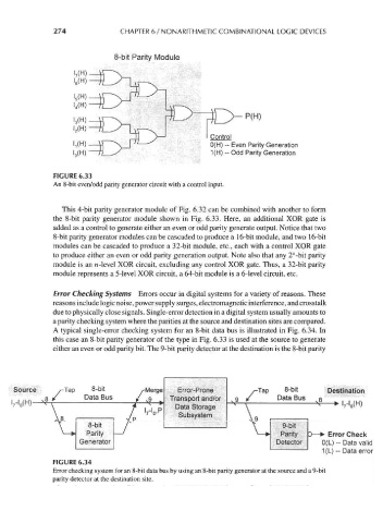
FIGURE 6.33
An 8-bit even/odd parity generator circuit with a control input.
This 4-bit parity generator module of Fig. 6.32 can be combined with another to form
the 8-bit parity generator module shown in Fig. 6.33. Here, an additional XOR gate is
added as a control to generate either an even or odd parity generate output. Notice that two
8-bit parity generator modules can be cascaded to produce a 16-bit module, and two 16-bit
modules can be cascaded to produce a 32-bit module, etc., each with a control XOR gate
to produce either an even or odd parity generation output. Note also that any 2"-bit parity
module is an n-level XOR circuit, excluding any control XOR gate. Thus, a 32-bit parity
module represents a 5-level XOR circuit, a 64-bit module is a 6-level circuit, etc.
Error Checking Systems Errors occur in digital systems for a variety of reasons. These
reasons include logic noise, power supply surges, electromagnetic interference, and crosstalk
due to physically close signals. Single-error detection in a digital system usually amounts to
a parity checking system where the parities at the source and destination sites are compared.
A typical single-error checking system for an 8-bit data bus is illustrated in Fig. 6.34. In
this case an 8-bit parity generator of the type in Fig. 6.33 is used at the source to generate
either an even or odd parity bit. The 9-bit parity detector at the destination is the 8-bit parity
Source e ^Tap 8-bit .rMerge Error-Prone ^Tap 8-bit Destination
8 / Data Bus / 9 Transport and/or v y & z: vO fc^ i i /i i\
^ \ t . :. P Data Storage -^-r ^ — ^ WH)
1
/
V \ i 8-bit xP '7 'O' Subsystem V 9-bit
\
w Parity -J / \—+ Parity D — ^ Error Check
Generator Detector 0(L) - Data valid
1(L) - Data error
FIGURE 6.34
Error checking system for an 8-bit data bus by using an 8-bit parity generator at the source and a 9-bit
parity detector at the destination site.