
Page 306 - Engineering Digital Design
P. 306
6.8 COMBINATIONAL SHIFTERS 277
RNy 00 01 11 10 R\ 00 01 11 10
T
R A, A 0 Y Y Y Y
T
T
T
3 2 1 0 n 0 '2 F
'3 '2 'o "1 "1 'o
00 0 I 3 I 2 I 1 I 0 Transfer
0 0 1 I 2 I, I 0 F s!1 1 '3 '2 'o 1 '2 "1 >3
"1 / 'o
0 1 0 I, I 0 F F s!2 1 7! ' 7 1
0 1 1
0 A A AA
\ n 0 N v 1 0
1 0 0 I 3 I 2 I., I 0 Transfer R\ oo 01 11 10 R\ oo 01 11 10
1 0 1 I 2 IT I 0 I 3 r!1
I, L F F 0 L F F F
1 1 0 L L L I, r!2
1 1 1 ID '3 "2 "1 rl3 i
"i 'o '2 '3 1 'o '3 '1 '2
(a) /
/ Y 1 /
(b)
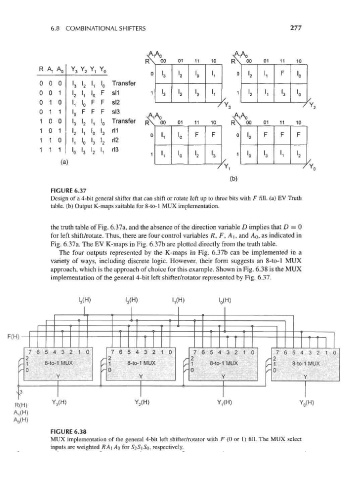
FIGURE 6.37
Design of a 4-bit general shifter that can shift or rotate left up to three bits with F fill, (a) EV Truth
table, (b) Output K-maps suitable for 8-to-l MUX implementation.
the truth table of Fig. 6.37a, and the absence of the direction variable D implies that D = 0
for left shift/rotate. Thus, there are four control variables /?, F, A\, and AQ, as indicated in
Fig. 6.37a. The EV K-maps in Fig. 6.37b are plotted directly from the truth table.
The four outputs represented by the K-maps in Fig. 6.37b can be implemented in a
variety of ways, including discrete logic. However, their form suggests an 8-to-l MUX
approach, which is the approach of choice for this example. Shown in Fig. 6.38 is the MUX
implementation of the general 4-bit left shifter/rotator represented by Fig. 6.37.
L(H) L(H) L(H) I 0(H)
F(H)
7 (5 ,5 4 3 : > 1 0 7 (3 5 *» 3 : > i ) < 7 e ! 5 **321 0 7654321 0
_ p ^_ 2 ^ 7 s- 2
/ - 1 8-to-1 MUX /- 1 8-to-1 MUX /r- 1 8-to-1 MUX r 1 8-to-1 MUX
/- 0 r- 0 /- 0 /- 0
\ r' \ f Y Y
x:J
Y 3(H) Y 2(H) >'i(H) Y 0(H)
R( H)
A,(H)
A 0(H)
FIGURE 6.38
MUX implementation of the general 4-bit left shifter/rotator with F (0 or 1) fill. The MUX select
inputs are weighted RA\ AQ for 52Si So, respectively.