
Page 343 - Engineering Digital Design
P. 343
314 CHAPTER 7 / PROGRAMMABLE LOGIC DEVICES
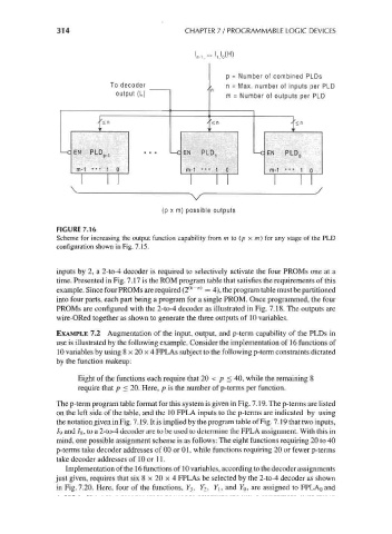
p = Number of combined PLDs
To decoder n = Max. number of inputs per PLD
output (L) m = Number of outputs per PLD
<n
EN PLD. EN PLD EN PLD
m-1 ••• 1 0 m-1 ••• 1 0 m-1 •• • 1 o
\ k . /
V
(p x m) possible outputs
FIGURE 7.16
Scheme for increasing the output function capability from m to (p x m) for any stage of the PLD
configuration shown in Fig. 7.15.
inputs by 2, a 2-to-4 decoder is required to selectively activate the four PROMs one at a
time. Presented in Fig. 7.17 is the ROM program table that satisfies the requirements of this
(k n)
example. Since four PROMs are required (2 ~ = 4), the program table must be partitioned
into four parts, each part being a program for a single PROM. Once programmed, the four
PROMs are configured with the 2-to-4 decoder as illustrated in Fig. 7.18. The outputs are
wire-ORed together as shown to generate the three outputs of 10 variables.
EXAMPLE 7.2 Augmentation of the input, output, and p-term capability of the PLDs in
use is illustrated by the following example. Consider the implementation of 16 functions of
10 variables by using 8 x 20 x 4 FPLAs subject to the following p-term constraints dictated
by the function makeup:
Eight of the functions each require that 20 < p < 40, while the remaining 8
require that p < 20. Here, p is the number of p-terms per function.
The p-term program table format for this system is given in Fig. 7.19. The p-terms are listed
on the left side of the table, and the 10 FPL A inputs to the p-terms are indicated by using
the notation given in Fig. 7.19. It is implied by the program table of Fig. 7.19 that two inputs,
/9 and /8, to a 2-to-4 decoder are to be used to determine the FPLA assignment. With this in
mind, one possible assignment scheme is as follows: The eight functions requiring 20 to 40
p-terms take decoder addresses of 00 or 01, while functions requiring 20 or fewer p-terms
take decoder addresses of 10 or 11.
Implementation of the 16 functions of 10 variables, according to the decoder assignments
just given, requires that six 8 x 20 x 4 FPLAs be selected by the 2-to-4 decoder as shown
in Fig. 7.20. Here, four of the functions, ¥3, Y 2, Y\, and YQ, are assigned to FPLAoand