
Page 345 - Engineering Digital Design
P. 345
316 CHAPTER 7 / PROGRAMMABLE LOGIC DEVICES
FPLA Inputs FPLA Outputs FPLA
P-terms "9 "a '7 'e "s '4 '3 '2 ', >o Y T 15 ... V T Y Y Y 0 Assigment
T
T
T
3
1
2
FIGURE 7.19
P-term table format for a multiple FPLA scheme to generate 16 functions of 10 variables by using six
8 x 20 x 4 FPLAs subject to the p-term conditions stated in Example 7.2.
FPLA2; the remaining four, Y-j, Yf,, Y 5, and ¥4, are assigned to FPLA] and FPLAs. Notice
that the active low tri-state enables for FPLAo and FPLAi are connected together and to a
single decoder output, as are those for FPLA2 and FPLA 3. By wire-ORing the outputs in
this manner, eight of the 16 output functions are each permitted to have up to 40 p-terms
with the remaining eight functions limited to 20 p-terms.
H
W )
f
'2
2-to-4 Decoder
3 2 1 0
Y 15,...,Y 12(H) Y n ..... Y 8(H) Y 7,..,Y 4(H) Y 3>...,Y 0(H)
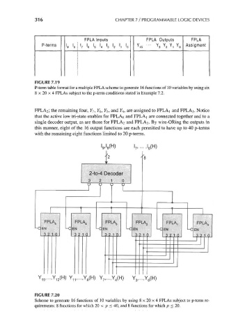
FIGURE 7.20
Scheme to generate 16 functions of 10 variables by using 8 x 20 x 4 FPLAs subject to p-term re-
quirements: 8 functions for which 20 < p < 40, and 8 functions for which p < 20.