
Page 356 - Engineering Digital Design
P. 356
7.7 INTRODUCTION TO FPGAs AND OTHER GENERAL-PURPOSE DEVICES 327
Six programmable
transmission gates
CLB
connection per matrix
with routing \ I interconnect point
channel \ F4 C4 G4 QY
G1
Y
C1
G3
CK CLB
C3
F1
F3
X
QX F2 C2 G2
Switch
Matrix
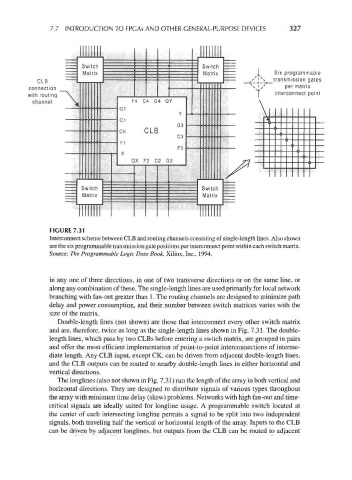
FIGURE 7.31
Interconnect scheme between CLB and routing channels consisting of single-length lines. Also shown
are the six programmable transmission gate positions per interconnect point within each switch matrix.
Source: The Programmable Logic Data Book, Xilinx, Inc., 1994.
in any one of three directions, in one of two transverse directions or on the same line, or
along any combination of these. The single-length lines are used primarily for local network
branching with fan-out greater than 1. The routing channels are designed to minimize path
delay and power consumption, and their number between switch matrices varies with the
size of the matrix.
Double-length lines (not shown) are those that interconnect every other switch matrix
and are, therefore, twice as long as the single-length lines shown in Fig. 7.31. The double-
length lines, which pass by two CLBs before entering a switch matrix, are grouped in pairs
and offer the most efficient implementation of point-to-point interconnections of interme-
diate length. Any CLB input, except CK, can be driven from adjacent double-length lines,
and the CLB outputs can be routed to nearby double-length lines in either horizontal and
vertical directions.
The longlines (also not shown in Fig. 7.31) run the length of the array in both vertical and
horizontal directions. They are designed to distribute signals of various types throughout
the array with minimum time delay (skew) problems. Networks with high fan-out and time-
critical signals are ideally suited for longline usage. A programmable switch located at
the center of each intersecting longline permits a signal to be split into two independent
signals, both traveling half the vertical or horizontal length of the array. Inputs to the CLB
can be driven by adjacent longlines, but outputs from the CLB can be routed to adjacent