
Page 497 - Engineering Digital Design
P. 497
10.12 DESIGN OF SIMPLE SYNCHRONOUS STATE MACHINES 467
State Memory
variable input logic
ABC = Q AQ BQ C change value
Q D
0
0 -» 1 1 Set
1 -*• 0 0
1 -» 1 1 Set Hold
ZiT if X
FSM to be designed Excitation Table
(a) (b)
\BC 11 \BC \BC
A\ 00 01 10 A \ X. 00 01 11 10 A\ 00 01 11 10
0 X 0 X 0 0 X X X X 0 1 0 0 1 1
1 X (7) X 0 1 X X X X 1 1 0 0 1
/ / /
D B
NS K-maps
(c)
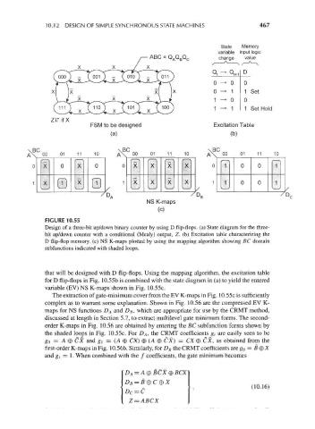
FIGURE 10.55
Design of a three-bit up/down binary counter by using D flip-flops, (a) State diagram for the three-
bit up/down counter with a conditional (Mealy) output, Z. (b) Excitation table characterizing the
D flip-flop memory, (c) NS K-maps plotted by using the mapping algorithm showing BC domain
subfunctions indicated with shaded loops.
that will be designed with D flip-flops. Using the mapping algorithm, the excitation table
for D flip-flops in Fig. 10.55b is combined with the state diagram in (a) to yield the entered
variable (EV) NS K-maps shown in Fig. 10.55c.
The extraction of gate-minimum cover from the EV K-maps in Fig. 10.55c is sufficiently
complex as to warrant some explanation. Shown in Fig. 10.56 are the compressed EV K-
maps for NS functions D A and D B, which are appropriate for use by the CRMT method,
discussed at length in Section 5.7, to extract multilevel gate minimum forms. The second-
order K-maps in Fig. 10.56 are obtained by entering the BC subfunction forms shown by
the shaded loops in Fig. 10.55c. For D A, the CRMT coefficients g, are easily seen to be
go = A © CX and g { = (A © CX) © (A © CX) = CX © CX, as obtained from the
first-order K-maps in Fig. 10.56K Similarly, for D B the CRMT coefficients are go = B © X
and g\ = 1. When combined with the / coefficients, the gate minimum becomes
(10.16)
Z=ABCX