
Page 494 - Engineering Digital Design
P. 494
464 CHAPTER 10 / INTRODUCTION TO SYNCHRONOUS STATE MACHINE DESIGN
PR(L)
"^ Q(H)
cK_fL_JLJLJLJl LLfLJn_n_Ji_n_n_n n n
D(H) | L
n
CL(L)
PR(L)
Q(H) _ i
(c)
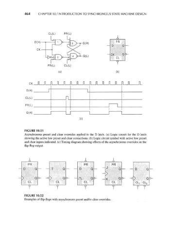
FIGURE 10.51
Asynchronous preset and clear overrides applied to the D latch, (a) Logic circuit for the D latch
showing the active low preset and clear connections, (b) Logic circuit symbol with active low preset
and clear inputs indicated, (c) Timing diagram showing effects of the asynchronous overrides on the
flip-flop output.
A A A
PR PR PR
D Q — — T Q — — D Q — ~ J Q _ _ D Q —
*v s.
> Q D- -C D- — JT. Q D- _ K Q o- -c 0-
CL CL CL CL PI fM
OLo
^xL-i
V V 9 u U U
1 1 1 1 II
FIGURE 10.52
Examples of flip-flops with asynchronous preset and/or clear overrides.