
Page 492 - Engineering Digital Design
P. 492
462 CHAPTER 10 / INTRODUCTION TO SYNCHRONOUS STATE MACHINE DESIGN
D+CK T+CK J+CK
D+CK T+CK K+CK S+CK
Transparency OsciHation if Oscillation if Oscillation if
for CK = 1 CK = 1 J = K = CK = 1 ST-CK = 1
(a) (b) (c) (d)
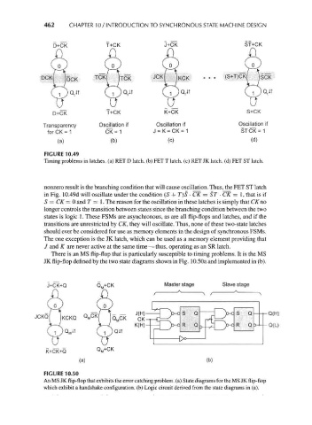
FIGURE 10.49
Timing problems in latches, (a) RET D latch, (b) FET T latch, (c) RET JK latch, (d) FET ST latch.
nonzero result is the branching condition that will cause oscillation. Thus, the FET ST latch
in Fig. 10.49d will oscillate under the condition (S + T)S • CK = ST • CK = 1, that is if
S — CK = 0 and T = 1. The reason for the oscillation in these latches is simply that CK no
longer controls the transition between states since the branching condition between the two
states is logic 1. These FSMs are asynchronous, as are all flip-flops and latches, and if the
transitions are unrestricted by CK, they will oscillate. Thus, none of these two-state latches
should ever be considered for use as memory elements in the design of synchronous FSMs.
The one exception is the JK latch, which can be used as a memory element providing that
/ and K are never active at the same time — thus, operating as an SR latch.
There is an MS flip-flop that is particularly susceptible to timing problems. It is the MS
JK flip-flop defined by the two state diagrams shown in Fig. 10.50a and implemented in (b).
J+CK+Q CL+CK Master stage Slave stage
JCKQ
K+CK+Q
(a) (b)
FIGURE 10.50
An MS JK flip-flop that exhibits the error catching problem, (a) State diagrams for the MS JK flip-flop
which exhibit a handshake configuration, (b) Logic circuit derived from the state diagrams in (a).