
Page 488 - Engineering Digital Design
P. 488
458 CHAPTER 10 / INTRODUCTION TO SYNCHRONOUS STATE MACHINE DESIGN
C o ; Q,->Q*i J K x
r^ o -» o 0 ^ Reset Hold Q^
D/ /•' -x Q I f~~~\
( P 0- 1 1 <£ Set ° D 0 17
(1)0,11 1 - o ^ 1 Reset
1 <* 1 D
TT 1 -» 1 ^ 0 Set Hold f ^i_J
W
D 'J '
Characterization of J = D K = D
State Diagram for the memory
FSM to be designed NS functions
(a) (b) (c)
D
-D*^- K Q >-
(d)
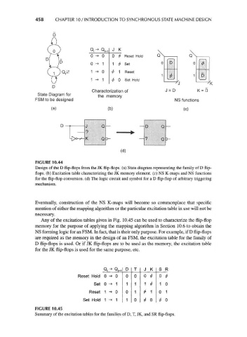
FIGURE 10.44
Design of the D flip-flops from the JK flip-flops, (a) State diagram representing the family of D flip-
flops, (b) Excitation table characterizing the JK memory element, (c) NS K-maps and NS functions
for the flip-flop conversion, (d) The logic circuit and symbol for a D flip-flop of arbitrary triggering
mechanism.
Eventually, construction of the NS K-maps will become so commonplace that specific
mention of either the mapping algorithm or the particular excitation table in use will not be
necessary.
Any of the excitation tables given in Fig. 10.45 can be used to characterize the flip-flop
memory for the purpose of applying the mapping algorithm in Section 10.6 to obtain the
NS forming logic for an FSM. In fact, that is their only purpose. For example, if D flip-flops
are required as the memory in the design of an FSM, the excitation table for the family of
D flip-flops is used. Or if JK flip-flops are to be used as the memory, the excitation table
for the JK flip-flops is used for the same purpose, etc.
Q t-> Q t+1 D T J K s R
Reset Hold 0 -> 0 0 0 0 0 #
^
Set 0 -> 1 1 1 1 1 0
1
Reset 1 -» 0 0 1 <* * 0 1
Set Hold 1 -> 1 1 0 0 I0
*
FIGURE 10.45
Summary of the excitation tables for the families of D, T, JK, and SR flip-flops.