
Page 484 - Engineering Digital Design
P. 484
454 CHAPTER 10 / INTRODUCTION TO SYNCHRONOUS STATE MACHINE DESIGN
State
g taj e variable Input logic
variable Q chan 9 e values
J K
0 0 Q t Hold
0 1 0 Reset
1 0 1 Set
1 1 Q t Toggle
Operation
Table
(a)
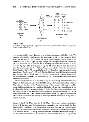
FIGURE 10.40
Generalized JK flip-flop definition expressed in terms of the operation table (a), the state diagram (b),
and the excitation table (c).
of an operation table, a state diagram, or an excitation table provided in Fig. 10.40. The
operation table in Fig. 10.40a reveals the four modes of JK flip-flop operation: Hold,
Reset, Set, and Toggle. Thus, it is seen that the JK type flip-flops operate in all the modes
common to SR, T, and D type flip-flops, though SR flip-flops (clocked SR latches) are
yet to be discussed. For this reason the JK flip-flops are sometimes referred to as the
universal flip-flops. The state diagram in Fig. 10.40b is best derived from the operation
table. For example, the Set (0 —> 1) branching condition follows from the Boolean sum
(Set + Toggle) = JK + JK = J, and the Reset (1 —»• 0) branching condition results from the
sum (Reset + Toggle) = JK + JK = K. The Set-Hold and Reset-Hold conditions result
from the sums JK + JK = K and JK + JK = J, respectively. However, given the set
and reset branching conditions, the sum rule in Eq. (10.3) can and should be used to obtain
the two hold conditions.
The excitation table for the JK flip-flops in Fig. 10.40c is easily derived from the state
diagram in (b). For example, the Reset-Hold branching path requires a branching condition
J that places a 0 and a 0 in the J and K columns of the excitation table. A 0 is used for
unspecified inputs in branching conditions. Similarly, a 1 and 0 are placed in the J and
K columns for the Set branching condition /. Notice that this excitation table bears some
resemblance to that of the combined excitation table for the basic cells in Fig. 10.15c, but
with two additional don't cares. The excitation table for the JK flip-flops will be used rather
extensively to characterize the memory in the design of FSMs that require JK flip-flops as
memory elements.
Design of the JK Flip-Flops from the D Flip-Flops The process used previously in the
design of T flip-flops from D flip-flops is now repeated for the case of the JK flip-flops
defined in Fig. 10.40 in terms of the operation table, state diagram, and excitation table.
Shown in Fig. 10.4 la is the state diagram representing the family of JK flip-flops, the FSMs
to be designed. Since a D flip-flop is to be used as the memory element in the design, its
excitation table must be used to characterize the memory and is provided in Fig. 10.41b.