
Page 486 - Engineering Digital Design
P. 486
456 CHAPTER 10 / INTRODUCTION TO SYNCHRONOUS STATE MACHINE DESIGN
(b)
Reset v Reset Reset
Hold Toggle Hold
(c)
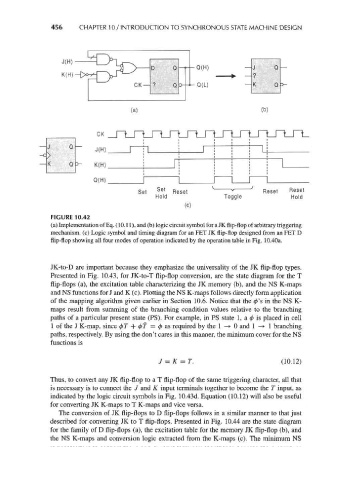
FIGURE 10.42
(a) Implementation of Eq. (10.11), and (b) logic circuit symbol for a JK flip-flop of arbitrary triggering
mechanism, (c) Logic symbol and timing diagram for an FET JK flip-flop designed from an FET D
flip-flop showing all four modes of operation indicated by the operation table in Fig. 10.40a.
JK-to-D are important because they emphasize the universality of the JK flip-flop types.
Presented in Fig. 10.43, for JK-to-T flip-flop conversion, are the state diagram for the T
flip-flops (a), the excitation table characterizing the JK memory (b), and the NS K-maps
and NS functions for J and K (c). Plotting the NS K-maps follows directly form application
of the mapping algorithm given earlier in Section 10.6. Notice that the 0's in the NS K-
maps result from summing of the branching condition values relative to the branching
paths of a particular present state (PS). For example, in PS state 1, a 0 is placed in cell
1 of the J K-map, since 0r + 07' = 0as required by the 1 —>• 0 and 1 —> 1 branching
paths, respectively. By using the don't cares in this manner, the minimum cover for the NS
functions is
J = K = T. (10.12)
Thus, to convert any JK flip-flop to a T flip-flop of the same triggering character, all that
is necessary is to connect the / and K input terminals together to become the T input, as
indicated by the logic circuit symbols in Fig. 10.43d. Equation (10.12) will also be useful
for converting JK K-maps to T K-maps and vice versa.
The conversion of JK flip-flops to D flip-flops follows in a similar manner to that just
described for converting JK to T flip-flops. Presented in Fig. 10.44 are the state diagram
for the family of D flip-flops (a), the excitation table for the memory JK flip-flop (b), and
the NS K-maps and conversion logic extracted from the K-maps (c). The minimum NS